International Journal of Advanced Research in Electrical, Electronics and Instrumentation Engineering
ISSN ONLINE(2278-8875) PRINT (2320-3765)
ISSN ONLINE(2278-8875) PRINT (2320-3765)
S.Karthick1, S.Dhivyapriya2, T.V.P.Sundararajan3
|
| Related article at Pubmed, Scholar Google |
Visit for more related articles at International Journal of Advanced Research in Electrical, Electronics and Instrumentation Engineering
Reconfigurable system design requires bit stream compression to minimize bitstream size and memory requirement. On the other hand, it enhances communication bandwidth and simultaneously reduces the reconfiguration time. The decodingaware compression technique facilitates improved compression and decompression efficiencies. Moreover, the decompression hardware for variable length coding matches the speed of the field-programmable gate array-based decoder for fixed-length coding. The three conditions which should be keenly watched during the bit stream compression are 1) overhead of decompression engine must be reduced through effective placement of bit streams 2) parameters should be carefully selected for bit stream compression 3) Bitmask compression and Run length encoding must be successfully combined for repetitive patterns. Our proposed technique outperforms the existing compression approaches by 15%, while our decompression hardware for variable-length coding is capable of operating at the speed closest to the best known field-programmable gate array-based decoder for fixed-length coding.
Keywords |
||||||||||||||||||||||||
| Dictionary Based Compression ,Bitmask Based Compression, RLE Based Compression, Bitstream Compression, Field Programmable Gate Array(FPGA). | ||||||||||||||||||||||||
INTRODUCTION |
||||||||||||||||||||||||
| Field Programmable Gated Arrays (FPGA) store configuration bitstream on memories which are usually limited in capacity and bandwidth.As FPGA are commonly used in reconfigurable systems and application specific integrated circuits (ASIC), configuration memory becomes a key factor in determining the number of IP cores that a system can be configured and the delay in reconfiguration. The bitstream compression algorithms solve memory constraint issue by reducing the size of the bitstreams and decompression accelerators increases the decoding speed by simple decoding logic. But there are very few algorithms that others both efficient compression ratio and fast decompression.Figure 1shows the typical flow of compressed FPGA bitstreamreconfiguration..The decompression hardware decodes and transfers the compressed bits from memory to configuration hardware which is then transferred to configurable logic blocks (CLB) memory. Compression ratio is the metric commonly used to measure effectiveness of a compression technique, defined as in Equation 1-1. | ||||||||||||||||||||||||
 |
||||||||||||||||||||||||
RELARED WORK |
||||||||||||||||||||||||
| There are numerous compression algorithms that can be used to compress configuration bitstreams. These techniques can be classified into two categories based on how the redundancies are exploited: format specific compression and generic bitstream compression. The compression techniques in the first category exploit the local redundancies in a single or multiple bitstreams by reading back the configured data and storing the differences by performing exclusive-OR (XOR) operation. These algorithms requires FPGA to support partial reconfiguration and frame readback functionality. Pan et al. [4] uses frame reordering in the absence of readback facility on FPGA. In this technique frames are reordered such that the similarity between subsequent frames configured is maximum. The difference between consecutive frames is then encoded using either Huffman based run length encoding or LZSS based compression. Another method proposed in the same article organizes and read back the configured frames. The frames are organized such that compressed bitstream contains minimal number of difference vectors and maximal readback of configured frames thus reducing the compressed frames significantly. Such complex encoding schemes tend to produce excellent compression ratio.However, decompression is a major bottleneck and is not addressed by Pan et al. [4].In sum, the compression technique in [4] achieves significant compression but incursfdrastic decompression overhead. On the other hand the approaches in second category [1] [9] try to maintain decompression overhead in an acceptable range but compromises on compression efficiency. Our technique tries to consider decompression bottleneck and overhead during the compression of bitstreams. The compression parametersare chosen such that compressed bitstreams are decode friendly while maintaining a goodcompression ratio. Fig. 2 shows our decode-aware bitstream compressionframework.Onthe compression side, FPGA configuration bitstream is analyzed for selection of profitable dictionary entries and bitmask patterns. The compressed bitstream is then generated using bitmask-based compression and run length encoding (RLE). Next, our decodeaware placement algorithm is employed to place the compressed bitstream in the memory for efficient decompression. During run-time, the compressed bitstream is transmitted from the memory to the decompression engine, and the original configuration bitstream is produced by decompression. | ||||||||||||||||||||||||
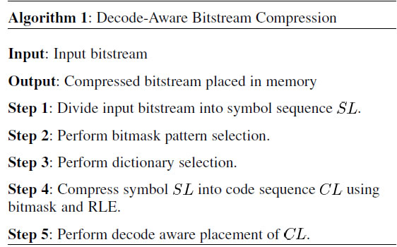
| Algorithm 1 outlines four important steps in our decode-aware compression framework (shown in Fig. 1):1) bitmask selection; 2) dictionary selection;3) integratedRLE compression; and 4) decode-aware placement. The input bitstream is first divided into a sequence of symbols with length.Then bitmask patterns and dictionary entries used for bitmask-based compression are selected. Next, the symbol sequence is compressed using bitmask and RLE. We use the same algorithm to perform the bitmask-based compression.The RLE Compression in our algorithm is also discussed in later chapter. Finally, we place the compressed bitstream into a decode friendly layout within the memory using placement algorithm. | ||||||||||||||||||||||||
 |
||||||||||||||||||||||||
DICTIONARY BASED COMPRESSION |
||||||||||||||||||||||||
| This section describes the existing dictionary-based approaches and analyzes their limitations. First, we describe the standard dictionary-based approach. Next, we describe the existing techniques that improve the standard approach by considering mismatches (hamming distance). Finally, we perform a detailed cost–benefit analysis of the recent approaches in terms of how many repeating patterns they can generate from the mismatches. This analysis forms the basis of our technique to maximize the repeating patterns using bitmasks. | ||||||||||||||||||||||||
Dictionary-Based Approach: |
||||||||||||||||||||||||
| Dictionary-based code-compression techniques provide compression efficiency as well as fast decompression mechanism. The basic idea is to take advantage of commonly occurring instruction sequences by using a dictionary. The repeating occurrences are replaced with a code word that points to the index of the dictionary that contains the pattern. The compressed program consists of both code words and uncompressed instructions. Fig. 3 shows an example of dictionary based code compression using a simple program binary. The binary consists of ten 8-b patterns, i.e., a total of 80 b. The dictionary has two 8-b entries. The compressed program requires 62 b, and the dictionary requires 16 b. In this case, the CR is 97.5%. This example shows a variable-length encoding. As a result, there are several factors that may need to be included in the computation of the CR, such as byte alignments for branch targets and the address-mapping table. | ||||||||||||||||||||||||
| Fig 3 illustrates a simple dictionary based compression with all words in dictionary and partial set of words in a limited dictionary. To obtain optimum compression ratio an intuitive approach would be to evaluate all possible values of word length (w) and dictionary size (d). Such an algorithm will take non polynomial time to reach efficient parameter combination.The largest limitation of the decoder in terms of speed is the number of bits it can process at a time. In this respect, compression methods like LZ78 most widely known through its variant LZW, have the distinct advantage of being able to read an entire input word at a time, as encoded words have the same length. However, the same technique has the disadvantage of having to dynamically generate and maintain the contents of the dictionary.A solution that targets both speed and simplicity would be to use a statistical dictionary that is computed based on the contents of the entire bitstream and is used throughout the entire decompression. Unlike the Huffman dictionary, there is no clear methodology for how such a dictionary can be created in an optimal way (at least not to the knowledge of the authors), but the characteristics of the bitstream make the choice an easy one. In particular, due to the high probability of occurrence of the zero symbol, the coding scheme degenerates into a bit -level RLE with minor modifications. | ||||||||||||||||||||||||
BITMASK- BASED COMPRESSION |
||||||||||||||||||||||||
| Bitmask-based compression is an enhancement on the dictionary-based compression scheme, that helps us to get more matching patterns. In dictionary-based compression, each vector is compressed only if it completely matches with a dictionary entry. As seen in Fig. 5, we can compress up to six data entries using bitmask based compression. The compressed data is represented as follows. Those vectors that match directly are compressed with 3 bits. The first bit represents whether it is compressed (using 0) or not (using 1). The second bit indicates whether it is compressed using bitmask (using 0) or not (using 1). The last bit indicates the dictionary index. Data that are compressed using bitmask requires 7 bits. The first two bits, as before, represent if the data is compressed, and whether the data is compressed using bitmasks. The next two bits indicate the bitmask position and followed by two bits that indicate the bitmask pattern. For example, the last data vector in Fig. 5 is compressed using a bitmask. The bitmask position is 11, which indicates the fourth even bit position from left. For this case, we have assumed fixed bitmasks, which are always employed on even-bit positions and hence only 2 bits are sufficient to represent the four positions in a 8-bit data. The last bit gives the dictionary index. The bitmask XORed with the dictionary entry produces the original data. In this example, the compression efficiency is 27.5%, based on the following formula expressed as percentage: | ||||||||||||||||||||||||
| Since existing approach does not handle don’t cares (“X”), in this example we have replaced all don’t cares by 1. Note that we could have replaced all don’t cares with 0’s as well. In that case, it will result in worse compression efficiency of 2.5%. A better compression efficiency can be achieved by selectively replacing the don’t cares with “0” or “1” instead of replacing all by 0’s (or 1’s). It is a major challenge to identify the selective replacement to generate the best possible compression efficiency. | ||||||||||||||||||||||||
RUN LENGTH ENCODING OF COMPRESSED WORDS |
||||||||||||||||||||||||
| The configuration bitstream usually contains consecutive repeating bit sequences. Although the bitmask-based compression encodes such patterns using same repeated compressed words, it is suggested in that run length encoding of these sequences may yield a better compression result. Interestingly, to represent such encoding no extra bits are needed. Note that bitmask value 0 is never used, because this value means that it is an exact match and would have encoded using zero bitmasks. Using this as a special marker, these repetitions can be encoded without changing the code format of bitmask-basedcompression.Fig. 5 illustrates the bitmask-based RLE. The input contains word “00000000” repeating five times. In normal bitmask-based compression these words will be compressed with repeated compressed words, whereas our approach replaces such repetitions using a bitmask of “00”. In this example, the first occurrence will be encoded as usual, whereas the remaining 4 repetitions will be encoded using RLE. The number of repetition is encoded as bitmask offset and dictionary bits combined together. In this example, the bitmask offset is “10”and dictionary index is “0”. Therefore, the number of repetition will be “100” (i.e., 4 ).The compressed words are run length encoded only if the RLE yields a shorter code length than the original bitmask encoding. In other words, if there are r repetitions of code with length and the number of bits required to encode them using RLE is bits, RLE is used only if bits. Since RLE is performed independently, the bit savings calculation during dictionary selection should be modified accordingly to model the effect of RLE. | ||||||||||||||||||||||||
Run-Length Hardware |
||||||||||||||||||||||||
| The Run-Length hardware is shown in Fig 7.It consists of a register to hold the current address to output; a down counter to count the length; an adder, to add the offsets to the previous value; and a mux to choose between a previous valued added to the offset and the new base value. The mux chooses the output of the base register when the down-counter equals zero. When a new code word arrives, the base value is written into the address register at the same time that the length is written into the downcounter. | ||||||||||||||||||||||||
DECOMPRESSION ENGINE |
||||||||||||||||||||||||
| The decompression engine is a hardware component used to decode the compressed configuration bitstream and feed the uncompressed bitstream to the configuration unit in FPGAs. As discussed previously, a decompression engine usually has two parts: the buffering circuitry is used to buffer and align codes fetched from the memory, while decoders perform decompression operation to generate original symbols. Since the decoders are well studied in previous literatures, we implement our bitmask and RLE decoder based designs in a successful way. | ||||||||||||||||||||||||
| The structure of our decompression engine for 8-bit memory is shown in Fig. 7. An “Assemble Buffer with a Left Shifter Array” (ABLSA) is employed to replace the original “Buffer with a Barrel Shifter” (BBS). The basic working principle of ABLSA is to use an array of left shift registers to buffer the power-two bitstreams separately. Since the code length in bitmask-based compression is uniquely determined by the first two bits of a code (is Compressed and is- Bit masked flags), we can easily obtain the length of a code by checking of front bits of stream CS and BS.Then, the shift register (or PT streams) that hold bits of the code is identified based on the binary representation of the code length. Finally, the original code is assembled in the assemble buffer and fed to the bitmask or RLE decoders. When some shifter becomes empty,it is guaranteed to be loaded correctly by our decompression algorithm. | ||||||||||||||||||||||||
Decompression Efficiency |
||||||||||||||||||||||||
| We measured the decompression efficiency using the time required to reconfigure a compressed bitstream, the resource usage and maximum operating frequency of the decompression engine. The reconfiguration time is calculated using the product of number of cycles required to decode the compressed bitstream and operating clock speed. We observed that our approach can operate at a much higher frequency and occupies only 60% area compared to original bitmask-based decompression engine. Since our approach has the identical bitmask decoding circuit of the original one, the improvementis due to our ABLSA as we expected. Compared withprevious techniques, our approach achieves almost the same operating speed with less area and also achieved 15%–20% better compression which means we can decompress more configuration information during the same amount of time. | ||||||||||||||||||||||||
SIMULATION RESULTS AND DISCUSSIONS |
||||||||||||||||||||||||
A. SIMULATION RESULT OF DICTIONARY BASED COMPRESSION |
||||||||||||||||||||||||
 |
||||||||||||||||||||||||
| The compacted scan chain network, which is mentioned in this section, reduces the scan depth of the scan chain, and reduces the test cost. Then combine the dictionary based compression scheme with the compacted scan chain network to achieve the high compression ratio and the fast application time. | ||||||||||||||||||||||||
B. SIMULATION RESULT OF DICTIONARY BASED DECOMPRESSION |
||||||||||||||||||||||||
 |
||||||||||||||||||||||||
| Here the bit stream which has been compressed is converted to its original size by subjecting it to the decompression engine. The simulation results shown here prove that the original data is retrieved from the compressed data. | ||||||||||||||||||||||||
C. SIMULATION RESULT OF BITMASK COMPRESSION AND DECOMPRESSION |
||||||||||||||||||||||||
 |
||||||||||||||||||||||||
| This have been developed using an efficient test data compression algorithm using bitmasks. A compressed code stores information regarding the mask type, mask location and the mask pattern itself. The mask can be applied on different places on a vector and the number of bits required for indicating the position varies depending on the mask type. | ||||||||||||||||||||||||
D. SIMULATION RESULT OF RLE BASED COMPRESSION |
||||||||||||||||||||||||
 |
||||||||||||||||||||||||
| A variation of Run-Length encoding perfectly meets the requirements for the address compression. A series of addresses with a common offset can be compressed into a codeword of the form base, offset and length. | ||||||||||||||||||||||||
E. SIMULATION RESULT OF RLE BASED DECOMPRESSION |
||||||||||||||||||||||||
 |
||||||||||||||||||||||||
| This strategy uses a more intensive decompression algorithm. It attempts to reorder the address data pairs in more optimal manner. Since the addresses must be decompressed and sent in addition to the data, our decompression strategies use both the address and data buses to send the decompressed code words. | ||||||||||||||||||||||||
CONCLUSION |
||||||||||||||||||||||||
| The existing compression algorithms either provide good compression with slow decompression or fast decompression at the cost of compression efficiency. In this paper, we proposed a decoding-aware compression technique that tries to obtain both best possible compression and fast decompression performance.. We also exploit run length encoding of consecutive repetitive patterns efficiently combined with bitmask-based compression to further improve both compression ratio and decompression efficiency. Our experimental results demonstrated that our technique improves the compression ratio by 10% to 15% while the decompression engine is capable of retrieving the compressed data without any loss. The configuration time is reduced by 15% to 20% compared to the best known decompression accelerator. In the future, we plan to investigate more placement algorithms that are compatible with other compression techniques such as Huffman coding, Goulomb coding and Arithmetic coding. | ||||||||||||||||||||||||
Tables at a glance |
||||||||||||||||||||||||
|
||||||||||||||||||||||||
Figures at a glance |
||||||||||||||||||||||||
|
||||||||||||||||||||||||
References |
||||||||||||||||||||||||
|


