ISSN ONLINE(2278-8875) PRINT (2320-3765)
ISSN ONLINE(2278-8875) PRINT (2320-3765)
Subhash Chander1, Dr. TK Jindal2
|
| Related article at Pubmed, Scholar Google |
Visit for more related articles at International Journal of Advanced Research in Electrical, Electronics and Instrumentation Engineering
Automated Fire control Systems (AFCS) is a sophisticated and critical segment of a typical Pulse detonation engine (PDE) rig. The relevant standards, safeties and redundancies were built by design to achieve successful missions. Primary emphasis is placed on the methodical approach required in the design of modernAFCS. This approach involves thorough analysis of the particular fire control problem at hand, establishment of the most suitable mathematical model, and computerization and realization of the built mathematical models through LABVIEW.The designed system was analysed rigorously validated against specifications. It was also tested in live firing after going through various qualifications/ verifications during various stages of development. The unit is operating satisfactory and proved its reliability during 70+ firings and will be utilized for future firings with enhanced capabilities.
Keywords |
| Pulse detonation engine, Automated Fire Control System, Data acquisition, Ignition system |
I. INTRODUCTION |
| The AFCS fire control and surveillance system design architecture provides flexibility for tailoring systems to meet different mission profiles. FCS systems are designed using small common modules. This partitioning of the different technologies ensures that the whole system runs efficiently. The system is durable and has been tested to endure extreme variations in temperature and the harshest environments. |
| AFCS is a key vital technology, which need to be developed for any pulse detonation rig. Stand-off safeties, reliability and mission criticalities need to be built in any PDE systems. The technology survey was carried out to create the specifications, which need to address. The key options for choices of implementation technologies was carried out and hence achieved to fabricate the hardware and software. The software based designed allowed a vast configurability coupled with safeties at various folds. LABVIEW based structured design of FCS is carried out. Figure 1 shows the schematics of PEC AFCS [1] showing all its major constituents and their interconnectivity. |
II. IGNITION SYSTEM |
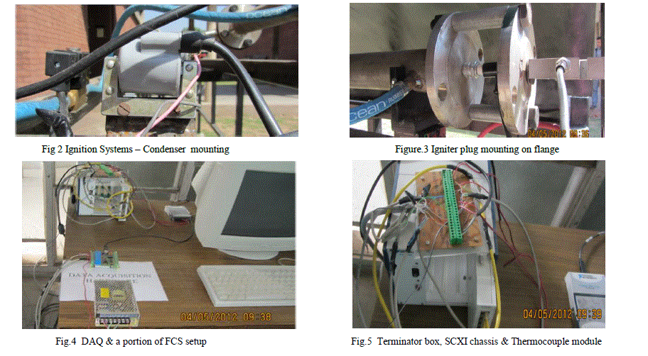
| The AFCS is coupled with ignition system, which consists of a 24 V DC Condenser (figure 2) and Igniter plug (figure 3) arrangement. The control for the igniter plug ignition is with the control circuit only, which is executed by AFCS. The Labview VI based controller gives an option to fire the igniter plug after the gas has been released into the system for the required specified amount of time. The O2 inlet and the C2H2inlet are near the Ignitor plug itself, which enables us to start the combustion, by imparting a high voltage spark to the gases. |
III. PDE CONTROL |
| The engine and support equipment was controlled by a National Instruments (NI) VI software program installed on a DAQ computer [2] in the control room (figure 4) with terminations (figure 5). The MC was linked to a NI PXI-1000B controller in the rig through an network connection to the PXI IP address. The program controlled engine operation by managing engine supply gas operation via ball valves located in the rig. A D-sub micro-connector based pulse generator also located in the control room controlled timing of trigger signals sent to both the fuel injectors and TPI via electrical relays located within the system. Also located within the control room were |
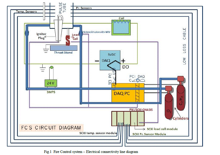 |
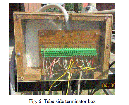
| 24 VDC and 220 VAC master power switches, and an emergency shutoff button. The electrical switches controlled electrical power within the rig for engine control and instrumentation equipment, such as temperature and pressure transducers connected through termination boxes (figure 6). The flow of gases inside pulse tube is controlled by solenoid based flow control valves with Non-return Valve for safety purposes. Additionally, The emergency shutoff button was provided as a safety feature and would disable rig by closing all supply gas ball valves,It will also interrupt fuel injection coupled with stoppage ofignition trigger signals. |
 |
| Data acquisition was controlled via the PC in the control room. The PC was linked to the SCXI-1000B controller mounted on the wall in the test cell, which in turn was linked to three NI data acquisition devices (DAQ) located on the engine stand. The PXI-6031E was 8channel, 16 bit card which collected operational parameters such as various engine temperatures and pressures, supply gas pressures and thrust at a rate of 10 kHzusing Labview programs.A data file path designated on the control program directed data in the form of an excel spreadsheet to a selected location. These data streams were used to calibrate the stand prior to the commencement of testing, and record thrust data during engine operation. A second file path designated on the control panel directed thrust, pr. & tempt data in the form of an excel spreadsheet to a selected location. Additionally, this data was streamed to the control program GUI for real-time monitoring. |
 |
V. DATA EXTRACTION |
| The above is the setup for data extraction. The extracted data is displayed online & saved in excel file for more detailed analysis in Matlab & GNUplot. |
VI. DATA ACCURACY |
| Data accuracy for the TMS/low pass filter system described above was computed using the root mean square function. The two major sources of error were introduced by the data acquisition [3] hardware (NI DAQ) and calibration/strain gauge fidelity of the TMS. National Instruments lists on their website detailed accuracy analysis of all supported DAQ equipment. [4] For the hardware installed on this rig, the company cites offset, system noise and temperature drift as the predominant error sources, and reports a system absolute accuracy of ± 0.377%. |
VII. AUTOMATED FIRE CONTROL SYSTEM SOFTWARE DEVELOPMENT FOR PDE: |
| Software is especially designed to give the commands for firing of PDE and record the outputs in correct sequences and timings. The software is written in Ni Labview working in robust test environment with NiDAQ and DOP libraries. The detailed analysis and plotting is carried out in Matlab. [1] The software is divided into three parts as below: |
| Firing control software |
| DAQ Analog input/output software module |
| Matlab based analysis utility |
| These are explained as below: |
| A. Firing control software |
| The software screen of National Instruments Labview [3] Firing control software (fig. 7) is as under: |
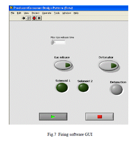 |
| The software allow user to select the gas release time in GUI Environment.Then Gas release button knob is pressed. The gas release is indicated by green lights thru Solenoid valves release feedback. After countdown, when „Detonationâ button is pressed, firing command is issued to igniter to detonate the accumulated gases using the program scheme, which is explained thru flow chart in figure 6. |
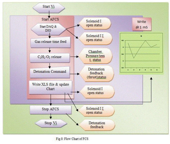 |
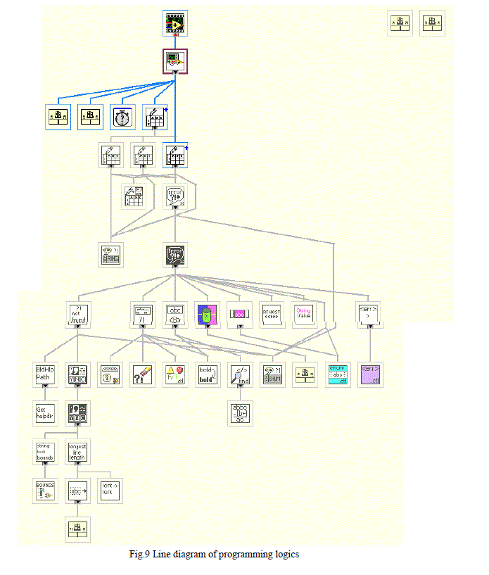
| The back end logics are clear from flow chart, which are self-explanatory. Same is also described by line diagram as shown in fig 9 plot. |
 |
| B. DAQ Analog input/output software module |
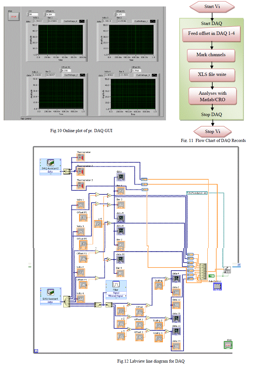
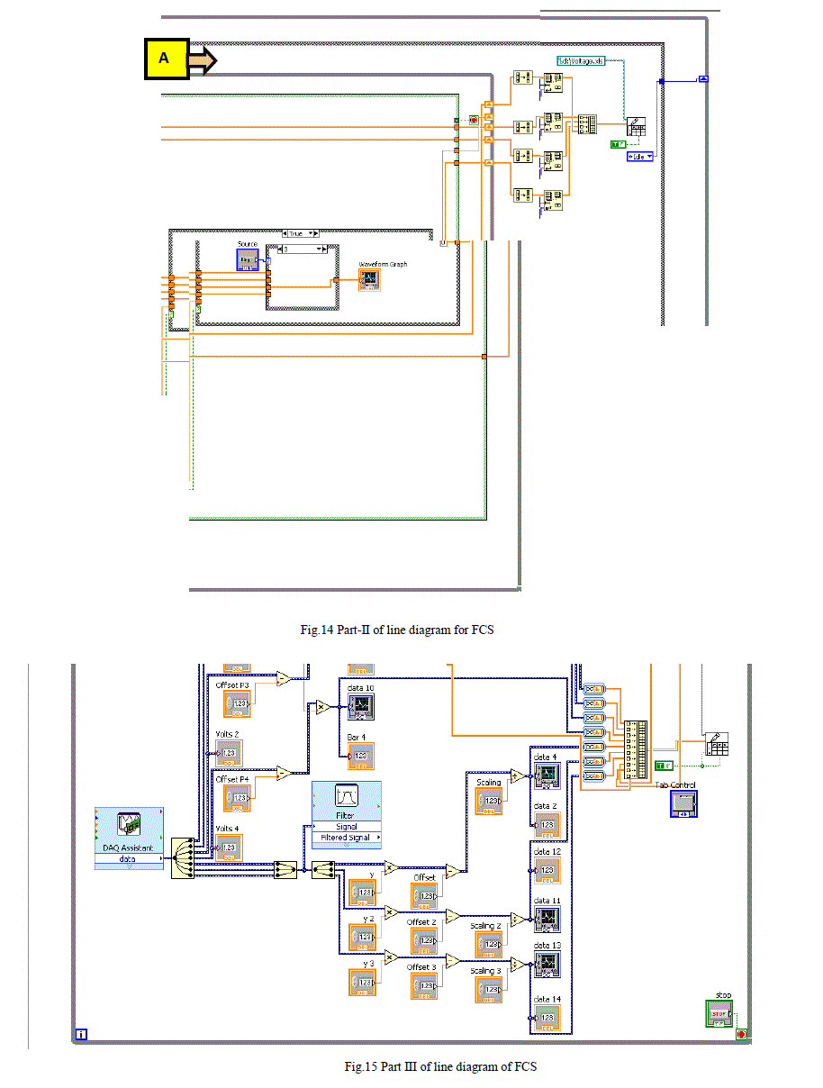
| NI DAQ [5] cards will generate Analog input commands in form of voltages, which will generate commands to open solenuiod valves, firing spark intitations through command signals. NI DAQ cards will also monitor pressures thru pressure sensors converted voltages, Thrust thru load cells converted voltages, temperatures thru thermocouple converted voltages sensed by DAQ and fed back to VI for display & storage to .xls file as shown in fig 10. It is visualy explained thru flowchart in fig 11. |
 |
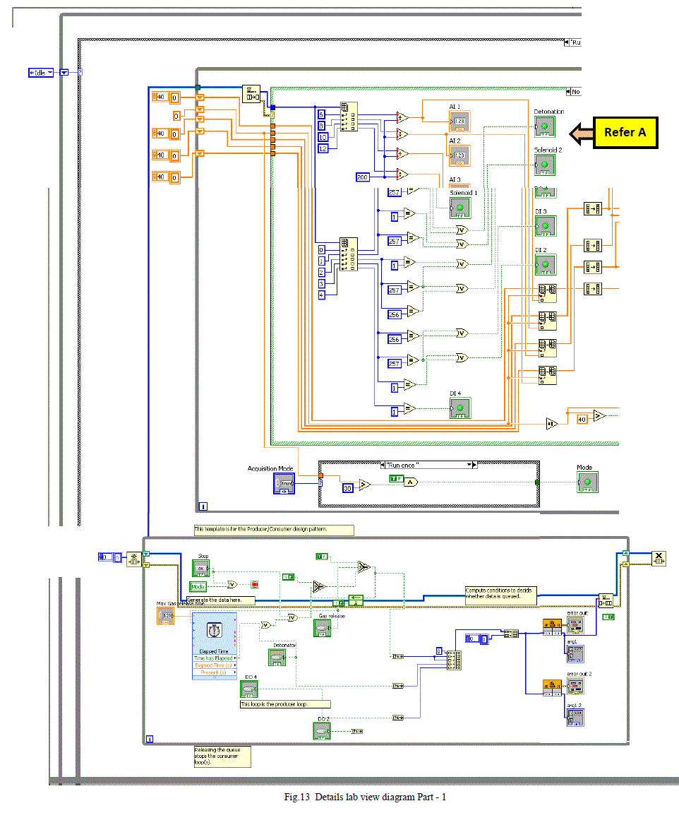
| Further details of their operations are visualized thru line diagrams in fig: 13 to 15 |
 |
 |
| C. Matlab based analysis Utility: |
| This explains the development of lab view based software AFCS for PDE analysing detonation, signal conditioning, display & .XLS file save for further analysis. |
| Matlab [6] program was written to analyse, filter, plot, compare and conclude the test achievements for further collaborations [2]. Since it is involving highly flammable fuels at closed vicinity of PDE system so appropriate check lists were developed for further enhancing g safeties as explained below: |
VIII. CONCLUSION |
| AFCS is a high end hardware/software component for PDE firing & analysing. It has been thoroughly examined thru software development life cycle in a interactive manner. It has been re-validated a lot in live observation of flight trials & further enhancement. It is being analysed to modify it for multi cycle operations & better filters in near future. |
ACKNOWLEDGEMENT |
| Authors are thankful to chairman Aerospace Engg. Dept. alongwith Director of PEC University of Technology, Chandigarh, India, Authors are also thankful to Director, TBRL for sponsored project in PDE. |
References |
|