ISSN ONLINE(2278-8875) PRINT (2320-3765)
ISSN ONLINE(2278-8875) PRINT (2320-3765)
N.Dhayanidhi1 and D.Muralidharan2
|
| Related article at Pubmed, Scholar Google |
Visit for more related articles at International Journal of Advanced Research in Electrical, Electronics and Instrumentation Engineering
The dynamic behavior of a DFIG grid connected, wind energy conversion system (WECS) is simulated using MATLAB. This paper presents the different fault conditions like line to ground faults, double line to ground faults and three phase faults. A fuzzy controller is integrated into the doubly fed Induction Generator (DFIG) Wind Energy Conversion System. The dynamic behavior for a DFIG Wind Energy Conversion system with fuzzy controller is simulated for different fault conditions and the results are compared to that of the system with PI Controllers. The comparison shows that the integrated fuzzy controller results in an improvement in the dynamic behavior of the system under transient conditions
Keywords |
| Doubly fed Induction Generator, Wind Energy Conversion System, and Fuzzy Controller. |
INTRODUCTION |
| The usage of conventional sources led to depletion of fossil fuel as well as carbon-di-oxide emissions ,great efforts have been done to produce electricity from renewable sources, especially wind power generation have found more attention .It is expected that wind energy will provide about 10% of the world’s electrical energy in 2020.Nowadays most of the wind forms are widely used doubly-fed induction generator (DFIG) technology with rotor and grid side converters rated at 20%-30% of the generator rating. Compared to the fixed speed induction generators, the Doubly- Fed Induction generator have the following advantages:1) it allows extracting maximum power from the wind, 2) fourquadrant converter topology is possible which allows the fast active and reactive power control and it improves the stability and power quality of wind turbine,3) mechanical stresses are limited, 4) capacitor banks are not needed to compensate the reactive power consumed by the fixed speed induction generators, 5)low converter power ratings, and 6) ability to supply power at constant voltage and frequency while the rotor speed varies. In this paper, a detailed model for representation of DFIG based wind farm in power system dynamics simulation is presented, ATLAB/SIMULINK software program is used for this study. This paper presents dynamic response analysis of DFIG based wind farm under various fault conditions using the Fuzzy Logic Controller. The objective of the work is to improve the dynamic response of DFIG. |
MODELLING OF DFIG |
| The stator voltage and rotor voltage of the doubly excited DFIG are supplied by the grid and the power converters respectively. Simulation of the realistic response of the DFIG system requires the modeling of the controllers in addition to the main electrical and mechanical components. The components considered include. (i) Turbine, (ii) drive train, (iii) generator and (iv) converter system. |
| A. Turbine |
| The turbine in DFIG system is the combination of hub and blades. Function of the turbine is to convert the kinetic energy of the wind to mechanical energy, which is given to the generator. Generally the detailed models of the turbine are used for the purpose of design and mechanical testing only. Inputs to the wind turbines are the wind speed, pitch angle and the rotor speed and the output from the wind turbine is the mechanical turbine. |
| B. Drive train |
| In stability studies, when the response of the system subjected to any disturbance is analysed, the drive train system should be modeled as a series of rigid disks connected via mass less shafts. Here the two mass drive train model is used for the stability studies of DFIG system and the dynamics can be expressed by the differential equations below |
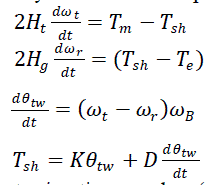 |
| Where, Hr and Hg(s) are the turbine and generator inertia, ωt and ωr (p.u) are the turbine and DFIG rotor speed, and Tsh is the shaft torque, Tm is the mechanical torque and Te is the electrical torque. θtw (rad) is the shaft twist angle, K(p.u/rad) the shaft stiffness, and D(p.u.s /rad) the damping coefficient. |
| C. Generator |
| The most common way of representing DFIG for the purpose of simulation and control is in terms of direct and quadrature axes (dq axes) quantities, which form a reference frame that rotate synchronously with the stator flux vector |
 (5) & (6) (5) & (6) |
| The equations can be expressed as |
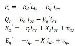 |
| Where s is the rotor slip; Ps is the output active power of the stator of the DFIG; Lss is the stator self-inductance; Lrr is the rotor self- inductance; Lm is the mutual inductance; ωs is the synchronous angle speed; Xs is the stator reactance; xs is the stator leakage reactance; xr is the rotor leakage reactance; Xs is the stator transient reactance; Ed and Eq are the d and q axis voltage behind the transient reactance, respectively;T0 is the rotor circuit time constant; ids and iqs are the d and q axis stator currents, respectively; Vds and Vqs are the d and q axis stator terminal voltages, respectively; Vdr and Vqr are the d and q axis rotor voltages, respectively; Qs is the reactive power of the stator of the DFIG. The voltage equations and the flux linkage equations of the DFIG are based on the motor convention. |
| D. Converter model |
| The converter model in DFIG system comprises of two pulse width modulation invertors connected back to back via a dc link. The rotor side converter (RSC) is a controlled voltage source as since it injects an AC voltage at slip frequency to the rotor. The grid side converter (GSC) acts as a controlled voltage source and maintains the dc link voltage constant. The converter power balance equation is: |
 (11) (11) |
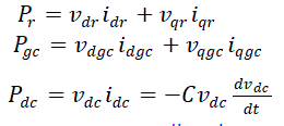
| The active power at RSC, GSC and DC link can be expressed as follows, |
 |
CONTROLLERS FOR DFIG (PI AND FUZZY CONTROLLER) |
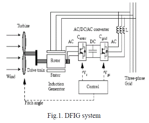
| Fig.1. shows a wind turbine connected to a DFIG. The AC-DC-AC converter is divided into two components: the rotorside converter (Crotor) and the grid-side converter (Cgrid). Crotor and Cgrid are Voltage-Sourced Converters that use forced-commutated power electronic devices (IGBTs) to synthesize an AC voltage from a DC voltage source. A capacitor connected to the DC side can act as the DC voltage source. A coupling inductor (L) is accustomed to connect Grid side converter to the grid. Here the three phase rotor winding is connected to Rotor side converter (Crotor) by slip rings, brushes and the three phase stator winding is directly connected with the grid. The power capture by the wind turbine is converted into electrical power by the induction generator and it is transmitted to the grid by the stator and the rotor windings. The control system generates pitch angle command and the voltage command signals Vgc for Crotor and Cgrid respectively so as to control the power of the wind turbine, the DC bus voltage , reactive power otherwise voltage on grid terminal. |
 |
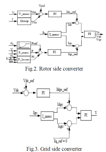
| The generic power control loop is illustrated in the fig.2. Called Rotor-Side Converter Control System. The actual electrical output power, precise at the grid terminals of the wind turbine, is added to the total power losses (mechanical and electrical) and is compared with the reference power obtained from the tracking characteristic. A Proportional Integral (PI) regulator is used to decrease the power error to zero. The output of the regulator is the reference rotor current (Iqr_ref) that must be injected in the rotor by rotor side converter (Crotor). This reference rotor current (Iqr_ref) that produces the electromagnetic torque (Tem). The actual Iqr component of positive-sequence current is compared to Iqr_ref and the error is reduced to zero by a current regulator (PI). The output of this current controller is the voltage Vqr generated by Crotor. The current regulator is assisted by providing the forward terms which forecast Vqr. The converter Cgrid is used to regulate the voltage of the DC bus capacitor. In addition, this model allows using Grid side converter (Cgrid) to generate or absorb reactive power. The control system, illustrated in the figure .3. Called Grid-Side Converter Control System consists of: |
| Measurement systems measuring the d and q components of AC positive-sequence currents to be controlled as well as the DC voltage Vdc. An outer regulation loop consists of a DC voltage regulator. The DC voltage regulator output is the reference current Idgc_ref for the current regulator. An inner current parameter loop consists of a current regulator. The current regulator used to controls the magnitude and phase angle of the voltage generated by converter C grid (Vgc) from the Idgc_ref produced by the DC voltage regulator and specified Iq_ref reference. The current regulator is assisted by providing the forward terms which predict the grid side converter output voltage. The magnitude of the reference grid side converter current Igc_ref is equal to |
 |
| The maximum value of this current is limited to a value defined by the converter maximum power at nominal voltage. When Idgc_ref and Iq_ref are such that the magnitude is higher than this maximum value the Iq_ref component is reduced in order to bring back the magnitude to its maximum value. |
 |
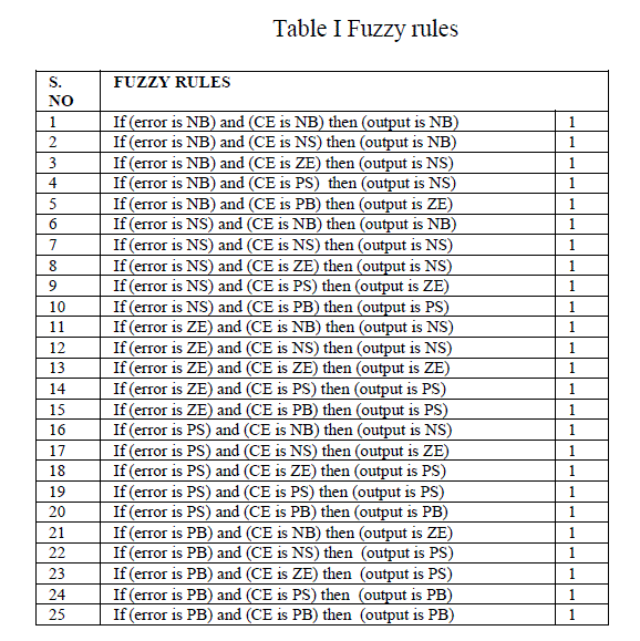
| For a good performance of DFIG based wind farm, four fuzzy logic controllers FLC1, FLC2, FLC3, and FLC4 are used. The PI controller in the dc bus voltage regulator is re-placed by the FLC1. The PI controller in the reactive power regulator is replaced by the FLC2. The PI controllers in current regulators of rotor side converter controller and grid side converter controller are re-placed by the FLC3 and FLC4respectively.the fuzzy sets have been defined as ;Negative Big NB, Negative Small NS, Zero Z, Positive Big PB, Positive Small PS. the fuzzy rules are shown in table I. |
 |
SIMULATION DIAGRAM |
| A 6*1.5 MW wind farm is connected to a 25 kV distribution system, which exports power to a 120 kV grid via a 30 km, 25 kV feeder. Wind farm uses a doubly-fed induction generator (DFIG) and an AC-DC-AC IGBT-based PWM converter. The stator winding of DFIG is directly connected to the 60 Hz grid while the rotor is fed at variable frequency through the AC-DC-AC converter. The doubly fed induction generator technology allows extracting maximum power from the wind for low wind speeds by optimizing the turbine speed. In this project the wind speed is maintain stable at 15 meter per second. The torque controller in control system is used to maintain the speed at 1.2 per unit. |
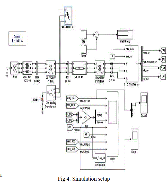 |
| Wind turbines using a doubly-fed induction generator consist of a wound rotor induction generator and an AC-DC-AC IGBT- based PWM converter. The switching frequency is chosen to be 1620 Hz. The stator winding is connected directly to the 60 Hz grid while the rotor is fed at variable frequency through the AC-DC-AC converter. The DFIG technology allows extracting more energy from the wind for low wind speeds by optimizing the turbine speed, while reducing mechanical stresses on the turbine during gusts of wind. The optimum turbine speed producing more mechanical energy for a given wind speed is proportional to the wind speed. |
RESULT AND DISCUSSION |
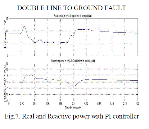
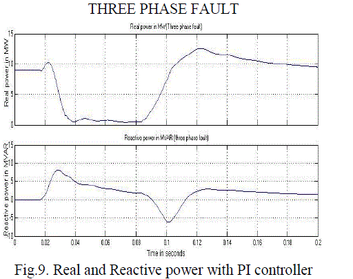
| The Dynamic behavior of above system for different faults such as single line to ground fault, lint to line fault and symmetrical fault are studied and the graphs for generated real power and reactive power are presented in the following figures |
SINGLE LINE TO GROUND FAULT |
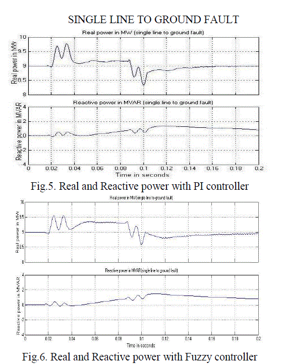 |
| From the above two figures the real and reactive power for single line to ground fault as shown (Fault period: 0.02 seconds to 0.1 seconds). It shows that during the single line to ground fault period the dynamic behavior of doubly fed induction generator with Fuzzy controller is improved as compared with PI controller |
DOUBLE LINE TO GROUND FAULT |
 |
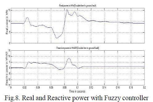 |
| From the above two figures the real and reactive power for double line to ground fault as shown (Fault period: 0.02 seconds to 0.1 seconds). It shows that during the double line to ground fault period the dynamic behavior of doubly fed induction generator with Fuzzy controller is improved as compared with PI controller. |
THREE PHASE FAULT |
 |
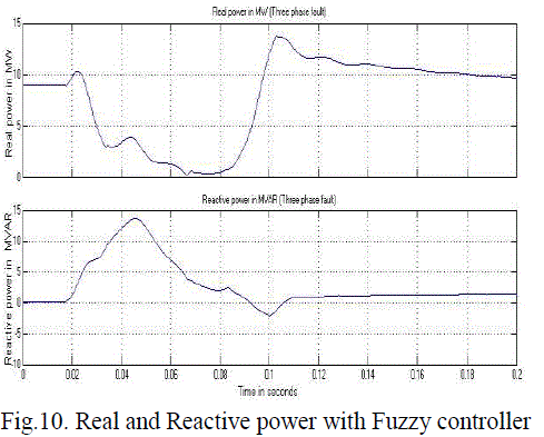 |
| From the above two figures the real and reactive power for three phase fault is shown (Fault period: 0.02 seconds to 0.1 seconds). It shows that during the three phase fault period the dynamic behavior of doubly fed induction generator with Fuzzy controller is improved as compared with PI controller. |
CONCLUSION |
| The dynamic behavior of a Doubly Fed Induction Generator grid connected Wind Energy Conversion system is simulated using MATLAB. The response of the system under fault condition has been compared graphically with PI controller and FUZZY logic controller. A comparison of the simulation results reveals that there is in improvement in the dynamic behaviour of the system with fuzzy logic controller. From the graphs it can be seen that fluctuations in the real and reactive power during the fault recovery are considerably reduced for the system with fuzzy logic controller. |
References |
|