ISSN ONLINE(2319-8753)PRINT(2347-6710)
ISSN ONLINE(2319-8753)PRINT(2347-6710)
Yuvaraj.S.A1, 2 Siddanna Gowd L.C2
|
| Related article at Pubmed, Scholar Google |
Visit for more related articles at International Journal of Innovative Research in Science, Engineering and Technology
Controller Area Network (CAN) is a real-time network that was initially conceived for automotive applications, but which is now becoming very popular as a fieldbus for automated factory environments because of its appealing features and low implementation costs. Controller Area Networks (CANs) are being used more and more today to support communications in real-time systems. However, under heavy traffic conditions the CAN access protocol may exhibit a quite unfair behavior, in particular, when the control applications require the same quality of service to be ensured to a number of different objects. In this paper, a new technique is proposed which is based on CAN and introduces few changes to the original protocol. Such a solution is able to ensure a very fair behavior, which resembles the one obtained in token based networks while maintaining, at the same time, the reduced access delays typical of CAN when operating in low traffic conditions. Furthermore, it preserves an optimum degree of compatibility with the existing devices and applications based on CAN
INTRODUCTION |
| Controller Area Network has been adopted by industry as the standard network technology to transmit data for sensors and actuators. This is due its fast response and high reliability for applications. CAN[1] is a serial communication protocol that efficiently supports distributed real time control with the high level of security .By using CAN wiring complexity can be avoid also. A rugged serial bus designed for industrial environments. Introduced by Bosch in 1986 for invehicle networks in cars, it is used in myriad applications including factory automation, building automation, aircraft and aerospace as well as in cars, trucks and buses. The CAN bus replaces bulky wiring harnesses with a two-wire differential wire. |
| CAN provide services at layers 1 and 2 of the OSI model and uses a broadcast method for placing frames on the wire. CAN provide low-speed, faulttolerant transmission of 125 Kbps up to 40 meters, which can function over one wire if a short occurs. Transmission without fault tolerance is provided up to 1 Mbps and 40 meters, and distances up to 1 km are achieved with bit rates of 50 Kbps. This interface/protocol was designed to allow communications within noisy environments. The CAN module is a communication controller, implementing the CAN 2.0 A/B protocol as defined in the BOSCH specification. The CAN protocol is an international standard defined in the ISO 11898. Beside the CAN protocol itself the conformance test for the CAN protocol is defined in the ISO 16845, which guarantees the interchangeability of the CAN chips. |
 |
| CAN is based on the “broadcast communication mechanism”, which is based on a message-oriented transmission protocol. Every message has a message identifier, which is unique within the whole network [3] since it defines content and also the priority of the message. It is easy to add stations to an existing CAN network without making any hardware or software modifications to the present stations as long as the new stations are purely receivers. This allows for a modular concept and also permits the reception of multiple data and the synchronization of distributed processes. In realtime processing the urgency of messages to be exchanged over the network can differ greatly; a rapidly changing dimension, e.g. engine load, has to be transmitted more frequently and therefore with less delays than other dimensions e.g. engine temperature. The priorities are laid down during system design in the form of corresponding binary values and cannot be changed dynamically. The identifier with the lowest binary number has the highest priority. |
| Bus access conflicts are resolved by bit-wise arbitration of the identifiers involved by each station observing the bus level bit for bit. This happens in accordance with the wired-and-mechanism, by which the dominant state overwrites the recessive state. All those stations (nodes) with recessive transmission and dominant observation lose the competition for bus access. All those "losers" automatically become receivers of the message with the highest priority and do not re-attempt transmission until the bus is available again. The “CAN base frame” supports a length of 11 bits for the identifier (formerly known as CAN 2.0 A), and the “CAN |
| extended frame” supports a length of 29 bits for the identifier (formerly known as CAN 2.0 B). CAN base frame format. A CAN base frame message begins with the start bit called "Start Of Frame (SOF)", this is followed by the "Arbitration field" which consist of the identifier and the "Remote Transmission Request (RTR)" bit used to distinguish between the data frame and the data request frame called remote frame. The following "Control field" contains the "IDentifier Extension (IDE)" bit to distinguish between the CAN base frame and the CAN extended frame, as well as the "Data Length Code (DLC)" used to indicate the number of following data bytes in the "Data field". If the message is used as a remote frame, the DLC contains the number of requested data bytes. The "Data field" that follows is able to hold up to 8 data byte. The integrity of the frame is guaranteed by the following "Cyclic Redundant Check (CRC)" sum. The "Acknowledge (ACK) field" compromises the ACK slot and the ACK delimiter. The bit in the ACK slot is sent as a recessive bit and is overwritten as a dominant bit by those receivers, which have at this time received the data correctly. Correct messages are acknowledged by the receivers regardless of the result of the acceptance test. The end of the message is indicated by "End Of Frame (EOF)". The "Intermission Frame Space (IFS)" is the minimum number of bits separating consecutive messages. Unless another station starts transmitting, the bus remains idle after this. |
| Unlike other bus systems, the CAN protocol does not use acknowledgement messages but instead signals errors immediately as they occur. For error detection the CAN protocol implements three mechanisms at the message level: |
| ï· Cyclic Redundancy Check (CRC): The CRC safeguards the information in the frame by adding a frame check sequence (FCS) at the transmission end. At the receiver this FCS is re-computed and tested against the received FCS. If they do not match, there has been a CRC error. |
| ï· Frame check: This mechanism verifies the structure of the transmitted frame by checking the bit fields against the fixed format and the frame size. Errors detected by frame checks are designated "format errors". |
| ï· ACK errors: Receivers of a message acknowledge the received frames. If the transmitter does not receive an acknowledgement an ACK error is indicated. |
| The CAN protocol also implements two mechanisms for error detection at the bit level: |
| ï· Monitoring: The ability of the transmitter to detect errors is based on the monitoring of bus signals. Each station that transmits also observes the bus level and thus detects differences between the bit sent and the bit received. This permits reliable detection of global errors and errors local to the transmitter. |
| ï· Bit stuffing: The coding of the individual bits is tested at bit level. The bit representation used by CAN is "Non Return to Zero (NRZ)" coding. The synchronization edges are generated by means of bit stuffing. That means after five consecutive equal bits the transmitter inserts a stuff bit into the bit stream. This stuff bit has a complementary value, which is removed by the receivers. |
| If one or more errors are discovered by at least one station using the above mechanisms, the current transmission is aborted by sending an "error frame". This prevents other stations from accepting the message and thus ensures the consistency of data throughout the network. After transmission of an erroneous message that has been aborted, the sender automatically reattempts transmission (automatic re-transmission). Nodes may again compete for bus access. The CAN protocol therefore provides a mechanism to distinguish sporadic errors from permanent errors and local failures at the station. |
| On the bit-level (OSI level one, physical layer) CAN uses synchronous bit transmission. This enhances the transmitting capacity but also means that a sophisticated method of bit synchronization is required. The CAN protocol regulates bus access by bit-wise arbitration. The signal propagation from sender to receiver and back to the sender must be completed within one bit-time. For synchronization purposes a further time segment, the propagation delay segment, is needed in addition to the time reserved for synchronization, the phase buffer segments. The propagation delay segment takes into account the signal propagation on the bus as well as signal delays caused by transmitting and receiving nodes. |
| Two types of synchronization are distinguished: hard synchronization at the start of a frame and resynchronization within a frame. |
| ï· After a hard synchronization the bit time is restarted at the end of the sync segment. Therefore the edge, which caused the hard synchronization, lies within the sync segment of the restarted bit time. |
| ï· Resynchronization shortens or lengthens the bit time so that the sample point is shifted according to the detected edge |
| The basis for transmitting CAN messages and for competing for bus access is the ability to represent a dominant and a recessive bit value. This is possible for electrical and optical media so far. Also power line and wireless transmission is possible. For electrical media the differential output bus voltages are defined in ISO 11898-2 and ISO 11898-3, in SAE J2411, and ISO 11992 (see below). With optical media the recessive level is represented by "dark" and the dominant level by "light". The physical media most commonly used to implement CAN networks are a differentially driven pair of wired with common return. The parameters of the electrical medium become important when the bus length is increased. Signal propagation, the line resistance and wire cross sections are factors when dimensioning a network. In order to achieve the highest possible bit rate at a given length, a high signal speed is required. |
II. REQUIREMENT OF THE ARCHITECTURE |
| The CAN protocol uses priority based packet transfer and there is no time sharing among between the device request. If the highest priority is always want to transmit the data, the other devices which are requiring will not be honored. To overcome this drawback a new approach is proposed in this project and it will work in any environmental condition. |
III. NEW PROTOCOL IMPLEMENTATION |
| CAN relays on medium access control (MAC) which is based carrier-sense multiple-access (CSMA) [2] technique. CAN quite different from Ethernet networks. In CAN a priority is associated to each transmitted frame, which is used to resolve possible collisions so that this network can be used in real-time systems characterized by tight timing constraints. In CAN, data and information are exchanged as communication objects (or, simply, objects), associated to identifiers that are used to tag each frame in the transmission phase. According to the protocol rules, the (numerically) lower the identifier of the frame is, the higher is the priority when competing to gain access to the shared communication medium. The rules by which a CAN node can access the shared communication medium are very simple: a frame can be transmitted when the state of the bus, which is monitored by each node, is found to be idle. A suitable arbitration [7,8] procedure based on the binary countdown technique ensures that, when two or more nodes collide, the contention is resolved by assigning the bus to the node which is transmitting the highest priority frame. If a transmission request is issued while the bus is busy, the requesting node waits until the bus turns to the idle state and then tries to send its frame. If several transmission requests are pending, a collision is unavoidable: in this case, the subsequent arbitration phase ensures that the node which is sending the object with the numerically lowest identifier wins the contention and keeps on transmitting. On their own, the losing nodes immediately interrupt their transmissions and switch to the receiving state. |
| In fact, when bus utilization grows and approaches 100%, the nodes transmitting high-priority objects can hog all the available bandwidth, excluding the other stations from accessing the bus. A modification of the CAN protocol called medium utilization state tracking (MUST) is introduced here, which provides very fair behavior without requiring the basic protocol to be changed in depth. In low traffic conditions the MUST technique behaves much like a CSMA network, while, when the offered load increases, it achieves performances similar to the token-based networks. |
| To overcome the drawbacks of CAN mentioned in the previous section, to analyze the behavior of such a network in more detail. In Fig. 2 sample traffic patterns are sketched for a CAN network in both low and heavy traffic conditions. Each frame has been labeled with the related identifier. Fig. 2(a) shows that, in low traffic conditions, nodes seldom collide and, even if they do, they very likely need not retry the transmission more than once (the probability of a second collision is negligible), so that very low delays (typical of CSMA networks) are experienced. |
 |
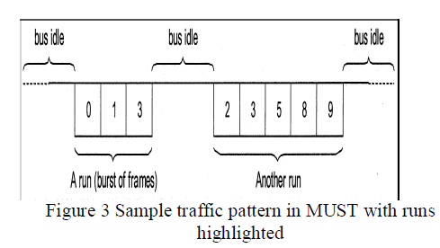
| By contrast, when the load offered to the network grows higher the traffic pattern on the bus turns into a sequence of frame bursts [Fig. 2(b)], each one containing one or more frames which are sent one after the other without the bus becoming idle between any pair of adjacent transmissions. The basic idea to enforce fair behavior in a conventional CAN network is to modify the original protocol so as to limit the number of times each object can be sent inside any one of the bursts mentioned above. In this way, the length of each burst is upper bounded and the same occurs for the transmission delays, as happens in the token-based networks. A run as a burst of frames is assumed, each one characterized by a different identifier, which are exchanged over the network without the bus becoming idle between any two adjacent frame transmissions, as shown in below. |
 |
| The MUST access scheme operates according to very simple rules: in fact, they are exactly the same as CAN, except that each object can be sent at most once in each run. Thus, the new protocol requires only one additional mechanism to detect an End of Run (EOR) condition. The easiest way to accomplish this task is by tracking the utilization state (either busy or idle) of the communication medium. In CAN, each frame transmission is followed by a period of time, called intermission (IMS), which consists of three recessive bits. After the intermission has completely elapsed, the bus is considered idle and each node can start transmitting a new frame, which begins with a start of frame (SOF) bit at the dominant level. For our purposes, when the bus is found recessive for a given additional time after the intermission, it is assumed to be completely idle. In practice, the concept of long intermission can be introduced, which consists of the conventional intermission field followed by an intermission extension (IMX) and can be used to denote an EOR condition, as shown in below. |
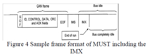 |
| Even though the intermission extension could include, in its simplest form, a single bit at the recessive level, robustness issues suggest making this field similar to the conventional intermission (i.e., three recessive bits). In this way, it is possible to detect an EOR condition by monitoring the state of the bus to find out when it becomes completely idle, with negligible effects on protocol complexity and with almost no penalties for communication efficiency. As stated previously, frames in a run have to appear in a strictly increasing identifier order, so as to improve network fairness. This requirement can be easily fulfilled by letting each node remember the identifier of the last frame which was exchanged on the bus (either read or written), for instance, by means of a suitable m register. The MUST mechanism can be described formally by means of the protocol automaton in figure below. |
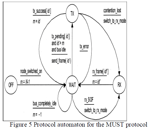 |
| The automaton shows that a node can send a new frame in the current run if and only if its identifier is strictly greater than m, otherwise it has to wait for the next run. When an EOR condition is detected, the m register is set back to the negative value -1, so as to enable a new run to be started. In this case, in fact, every object can be sent again, irrespective of its identifier. It can be easily proven that all the frames which are waiting for transmission are ordered by the access mechanism described above and the shape of the traffic pattern on the bus effectively consists of a sequence of runs. As a consequence, MUST features a round-robin service policy, which resembles the one provided by many token-based networks and ensures a fair and deterministic behavior in a number of situations where conventional CAN is not able to satisfy such a requirement. |
| Frame time depends only on the size of the frame and the bit rate adopted in the network, and its evaluation is a trivial issue. On the contrary, when an arbitrary message generation pattern is considered there is in general no upper bound for the queuing time, whatever the access mechanism adopted in the network. The queuing time is effectively reduced to zero and the transmission time can be evaluated very simply as the sum of the access time and the frame time [4]. Such an assumption fits in well with many hard-real-time systems: in fact, if a new value of an object becomes available before the old one has been delivered, then the deadline of the related data has certainly been exceeded, thus violating the timing constraints of the controlling application. To evaluate the worst case delay a frame can experience in a network based on the MUST technique, it should be noted that the longest permitted run corresponds to a sequence of frames, being the maximum number of data streams (i.e., different objects) which can be defined in the system. In fact, according to the MUST access rules, each object (characterized by a unique identifier) can be sent at most once per run. Two different situations are |
| ï· I > j: In this case, object can be sent in the current run. The transmission of object can be delayed by the objects whose identifier is strictly lower than (because they have a higher priority, according to the CAN protocol) but strictly higher than (because of the MUST access rules). |
| ï· I < j: In this case, object cannot be sent in the current run. Hence, it has to wait for the beginning of the next run. The delay which object can incur is given by the sum of the time taken to complete the current run (at most N-j frame times), the duration of IMX (few bit times) and the time spent in the next run waiting for higher priority frames to be sent (at most i frame times). This gives as a result a maximum access delay equal to N+i-j frame times. |
| A slightly different treatment is reserved for the (unusual) case when other nodes start transmitting at exactly the same time as the transmission of object begins, after each transmitting node detected a bus idle (or completely idle) condition. |
| ï· i is the smallest value among the identifiers of all the objects involved in the collision: in this case, object is sent immediately |
| ï· i is not the smallest value: this condition is similar to case 1 described above. |
3.1 MUST MECHANISM WITH SEVERAL PRIORITY CLASSES |
| The round-robin service policy provided by the MUST technique, though appealing from several points of view is likely to be useless in the real-time environments for which CAN was conceived. In many cases, in fact, the scheduling policy must be selected on a per-stream basis, so that the deadlines of the different objects which are defined in the system are always respected. A very suitable solution is to have a (usually small) number of priority classes to which the different objects are assigned. The access mechanism must guarantee the same QoS for all the objects belonging to the same class. This means that all the objects of a given class should experience similar delays and they are granted the same amount of bandwidth, though they still have precedence over the objects belonging to the lower priority classes. |
| To define the concept of a MUST priority class in a more formal way, let be the set of the object identifiers in the network. Since it is assumed that the underlying communication system is basically a CAN network adopting standard 11-b identifiers I = {id|0 <= id <= N-1}, where N = 2032 (or 2048 in newer controllers). It is worth remembering that in CAN the object identifier also specifies the priority of the frame, |
 |
| which is used in the arbitration phase to resolve the collisions on the bus. |
3.2 IMPLEMENTATION ISSUES |
| The simplest solution to implement the MUST access scheme over a CAN network is to use the first k bits of the identifier to encode the priority level of the object, so that M=2k classes are made available. If standard 11-b identifiers are used, up to 211-k different objects are defined inside each group and the priority level of an object id is given by p=|id√211-k |(where [x] indicates the greatest integer lower than or equal to x). For example, if one bit only is devoted to encode the priority level, the classical scheme that is based on the availability of high and low priority frames are obtained. Instead, in the case when CANopen is selected as the application level protocol, a MUST system based on 16 different priority classes could be a more suitable solution. |
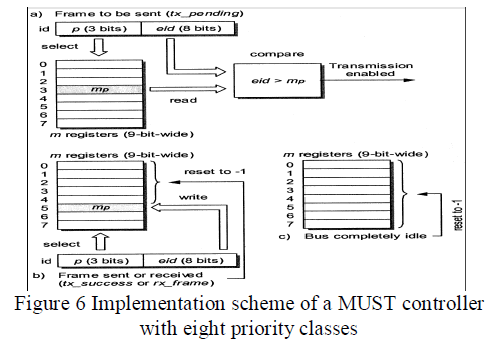
| In MUST, every node must keep a separate register for each priority level, so as to store the value of the mp parameter. If the encoding scheme described above is adopted, each register mp is (11- k) -b-wide and stores the part of the identifier which does not depend on the priority level (i.e., the least significant bits). Since the value -1 has to be managed too, the mp registers must be able to store signed quantities represented on (12 - k)b. In particular, Fig. 6(a) highlights the blocks involved in deciding whether a frame can be sent in the current run or if it has to wait for the next run. The other two schemes, instead, show how the mp registers are updated when either a frame is exchanged correctly [Fig. 6(b)] or the bus is detected to be completely idle [Fig. 6(c)]. |
IV. CONCLUSIONS |
| Though CAN has many interesting features, in heavy traffic conditions it may exhibit a quite unfair behavior. In particular, it is not possible to provide the same QoS to a given set of objects (this holds for both real-time and nonreal-time exchanges), nor to ensure deterministically bounded transmission delays in every traffic condition. In this paper, a modification of the basic medium access technique of the CAN protocol has been introduced, which ensures a very fair behavior in all operating conditions. In particular, it provides a number of priority classes and, for each class, a round-robin service policy is granted to the different communication objects. The main advantage of MUST with respect to other fairness control techniques which have been proposed for CAN is that object identifiers do not have to be reassigned dynamically, and hence it can easily be used together with the currently available applicationlevel protocols which are based on CAN. |
References |
|