International Journal of Innovative Research in Science, Engineering and Technology
ISSN ONLINE(2319-8753)PRINT(2347-6710)
ISSN ONLINE(2319-8753)PRINT(2347-6710)
L.Devi, C.H. Saibabu, S.Sivanagaraju
|
| Related article at Pubmed, Scholar Google |
Visit for more related articles at International Journal of Innovative Research in Science, Engineering and Technology
Economics plays a major role in the application of reliability concepts and attainment of an acceptable level of reliability. Reliability is not free but poor reliability of electric power supply usually costs much more than good reliability. It is therefore important to determine the optimal reliability level at which the reliability investment achieves. The best results in reducing the customer damage costs or Lost of load value due to power supply interruptions. In this paper the effect of installation of VSC- tapping station cost beneficial or not is investigated and compared at the load point evaluating the value of lost of load.
Keywords |
| reliability, customer damage cost, lost of load value, tapping station |
I. INTRODUCTION |
| One of cost/ benefit analysis is to develop techniques which can appropriately evaluated the cost of value of loss of load or customer damage costs due to supply interruptions [5]. Generally the loss of any single generating unit or transmission line should not cause load interruption. This criterion does not explicitly consider the probability of component failures and the value of service to customers. It can therefore result in provide additional capacity. The criterion provides no economic input to the cost associated with a particular expansion to customers. The cost of HVDC system is depending upon the length of the transmission line, transmission voltage, conductor size, transmission losses [1]. |
| Transmitting power from sending end to receiving end to meet the load demand. If any line of DC link under gone failure state or any deficiency in generation of power does not meet the load demand [ 2,3 ]. In such a case installing the tapping station at the middle of the transmission line. The effect of tapping station on reliability indices of bipole HVDC transmission system is discussed in [12]. Reliability models of HVDC transmission systems are presented in [2]. There are various methods to find the reliability of composite system. One of the best method is Markov modelling. This particular method is applicable to the system consists ‘n’ number states. In this method Markov modelling is used to find the reliability values of each component of HVDC transmission system, using these value lost of load of bipole VSC-HVDC transmission system is evaluated without and with installing the tapping station[ 6]. |
II BASIC METHODOLOGY |
| In this paper Markov modelling approach is used to take account the distribution of component failure over time. It is possible to compute the reliability parameters as the long term probability of the system being in a given state by solving a linear differential equation system. The graphical model constructed to display all possible transition paths between states is called state space diagram [9]. |
| A Markov model can be applied to systems whose random behaviour varies either discretely or continuously with time. In this paper Markov modelling has been adapted. fig 1 shows a basic example of two state system. |
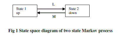 |
| In Fig1 there are two states up state (state 1) and down state (state 2). There are two transitions associated with each component, the first L representing the failure process and the second M representing the repair process. This model implies that the component becomes operational and in service immediately following the repair acting. The duration of the failure is limited to the time it takes to install the spare unit rather than to repair of the equipment itself [4 ]. |
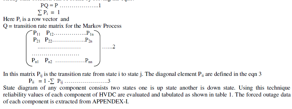
| In this paper, only the equations for calculating the steady state solution of the system are presented. This solution gives the probability of being in a certain state after an infinite time in the system. It can be shown that this steady state solution can be found by solving the eqn1. |
 |
 |
III BASE CASE |
| The system shown in Fig 2 is used to illustrate the operation of an HVDC transmission system with a VSC tapping station [11]. The transmission capacity of 500kV transmission system and the generating capacity at the sending end are assumed to be 1200MW and the load at the receiving end is assumed to be constant and equal to 960MW. |
| The per unit system is used in the studies with a base of 1200MVA. The transmission line capacity is equal to 1p.u. and the transmitted power on the line can vary between 0 to 1p.u. The total generation (1.2p.u) and is more than the transmission line capacity (1p.u) and the tapping station can assist the system when there is no congestion on the transmission line. The length of the transmission line is 500km and the tapping station is installed at the middle of the line (i.e., 250km from each end) with 0.2p.u value or 240MW capacity. The system load at the receiving end is 0.8p.u. It is assumed that the generating system at the sending side is fully reliable. |
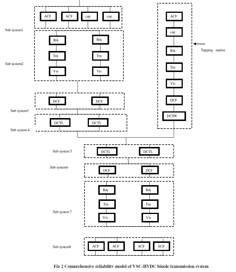
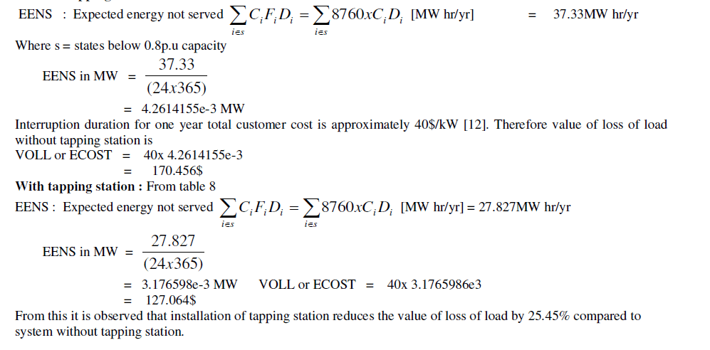
| In this chapter cost benefit analysis of the effect of tapping station on reliability of VSC-HVDC bipole transmission system is evaluated and compared by finding the lost of load value. A hypothetical model of VSC-HVDC bipole transmission system is as shown in the Fig 2. For Fig 2 reliability models are prepared to evaluate the value of lost of load . |
IV RELIABILITY MODELING OF COMPONENTS OF VSC_HVDC SYSTEM WITH TAPPING STATION |
| A hypothetical 500kV VSC-HVDC transmission system with VSC tapping station is as shown in the Fig 2 The typical structure of VSC-HVDC transmission and the location of the major power components are shown in the Fig 2. The system configuration of VSC-HVDC includes converter valves, converter transformer, power filters, reactors and transmission lines, etc. This system has also three segments sending end, receiving end, tapping station [ 11 ]. |
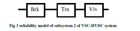
| Sending End: In the sending end of VSC-HVDC consists subsystems 1,2,3 and 4. Where in subsystem 2 components Brk, Trn and vlvs are combined to form a pole. Reliability model of subsystem 2 of VSC- HVDC is shown in the Fig 3. |
 |
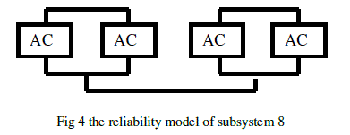
| Receiving end: The receiving end of VSC-HVDC subsystems 5,6, 7 and 8 are similar to subsystems 4,3,2 and 1. Except subsystem 8. In VSC HVDC at inverter side IGBTs has, there is no need of capacitors for reactive power compensation. Therefore the components of subsystem 8 consists four ACF are connected in Parallel. The reliability model of subsystem 8 is as shown in the Fig 4. |
 |
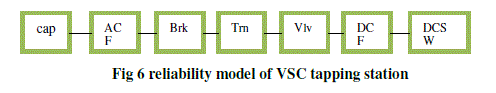
| Tapping station: Components of tapping station is as shown in the Fig 5. Corresponding reliability model is as shown in Fig 6. |
 |
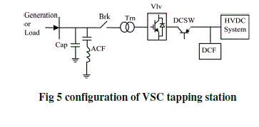 |
| The VSC configuration, as shown in Fig 5 is composed of Vlvs, DCSWs, Brk, Trn, ACF, cap, and DCF. Since a failure of any one of these components results in the failure of the entire tapping station, the reliability model is composed of series blocks, as shown in Fig 6. |
 |
V ANALYSIS AND PROCEDURE |
| The reliability models associated with the sending end, the receiving end, and the tapping station are combined to obtain the reliability model of the entire system. In order to analyze the final reliability model, different methods, such as the COPT-based risk model, network reduction, minimal cut sets, and Monte Carlo simulation could be used [10]. In this paper network reduction method is used to find the final reliability model. |
VI DESCRIPTION OF TABLES |
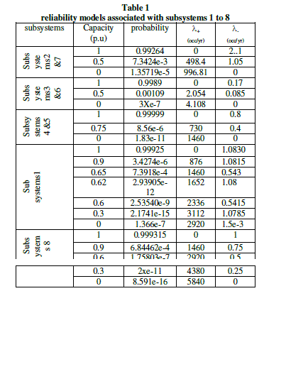
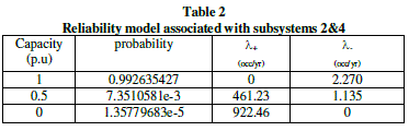
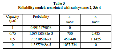
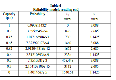
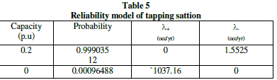
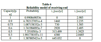
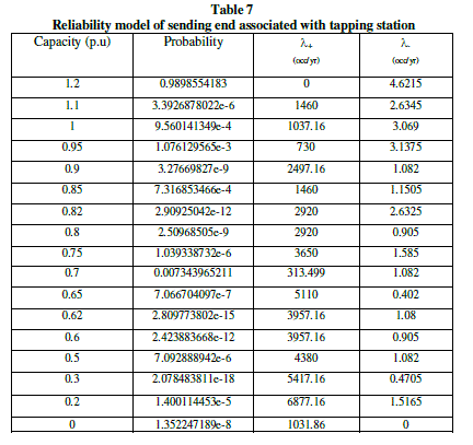
| The analysis procedure is based on the assisting unit approach. In the first stage, the reliability models of subsystems 1 to 8 are developed as shown in table 1. This table shows the probability of each state and the associated transition rates to the higher and lower available capacity levels [6,7]. At the next stage, the models associated with subsystems 2 and 4 are combined as shown in table 2. This model is then convolved with the model of subsystems 3 as shown in table 3. At the next stage 2,3, and 4 are combined as shown in table 4. The final stage on the modeling of the sending end segment involves adding the model of subsystem 1 to the equivalent model of subsystem 2 to 4. The resulting model which represents the sending end is as shown in table 4. COPT of the tapping station is givel in table 5 as assuming 0.2pu. Fully reliable generation capacity at the tapping station. The next stage involves adding the assistance of the tapping station to the COPT of the assisting system (table 4) the resulting COPT is shown in table 6. Note that table includes some states with the assistance capacity level of more than 1pu. The higher capacity of states is capped at 1p.u. of line capacity [11]. Final stage is combined the COPT shown in table 7 with the reliability model of the receiving end segment which is identical to sending end except the subsystem 8, consists four ACFs are connected in parallel is as shown in the Table 6. The final COPT of VSC-HVDC bipole transmission system with tapping station as shown in table 8. |
 |
 |
 |
 |
| In order to know the effect of tapping station on value of loss of load, the case without tapping station is considered. The reliability model of VSC-HVDC without tapping station is obtained by combining the two models ( table 4 and 6) obtained equivalent model is shown in table 9. |
 |
VII RESULT AND ANALYSIS |
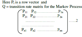
| Forced outage data of each component is taken from APPENDEX-I and APPENDEX-II, Using Markov modelling the reliability values of each component of HVDC are evaluated. From the tables 8 and 9 value of loss of load of VSCHVDC transmission system without and with VSC tapping station at the middle of the transmission line with tapping station capacity 0.2p.u. and load level Capacity 0.8p.u is calculated as follows Without tapping station: From table 9 |
 |
 |
 |
VIII CONCLUSIONS |
| The paper presented an evaluation methodology for the reliability of a VSC-HVDC transmission system with a VSC tapping station. A comprehensive reliability model associated with a VSC-HVDC system with a tapping station was developed taking into account the impacts of different system components. The proposed model was simplified by using basic reliability engineering concepts. The result of the numerical analysis shows that a tapping station can significantly improve the value of loss of load at the load point. Therefore installation of tapping station is cost benefit based on the load curtailments at the load points. |
 |
References |
|