International Journal of Innovative Research in Science, Engineering and Technology
ISSN ONLINE(2319-8753)PRINT(2347-6710)
ISSN ONLINE(2319-8753)PRINT(2347-6710)
Amol B. Rabade1, Vijay V. Doijad1, A.S. Todkar2
|
| Related article at Pubmed, Scholar Google |
Visit for more related articles at International Journal of Innovative Research in Science, Engineering and Technology
Special purpose machine are widely used for special kind of operations, which are not economical on conventional machines. It is design for getting higher accuracy at desired condition. Face milling in industrial component is followed by a milling process. In the initial core bore is develop on the component with the help of required tool material. A Special Purpose Machine introduced here can be operated manually or automatically, as per the condition or a mechatronic based system can be developed that will work with different speed. A SPM can be developing with two separate units which perform milling & boring operation sequentially. SPM introduced here is automatically start operation by sensing work piece on table; it helps in start & end of cycle. Milling Machine performs first milling operation of face of 105 x 135mm size and then boring machine for ø41.30H7 × 20mm deep cylinder block. In this the job is machined on two machines and two fixtures are used and operation is performed, hence it takes 10 min. to completion of one job. In this method Bore to face perpendicularity not maintained, so accuracy is low. The production rate is very low due to time required for two times loading and unloading of job, operational accuracy required. The manpower is required is more & skilled. In order to successfully come up with these problems, company decided to develop Special Purpose Machine. It will save production time and increase the production rate.
Keywords |
| Milling,Boring,spindle,Special purpose machine, Drive mechanism. |
INTRODUCTION |
| A design engineer has to improve existing manufacturing technique by implanting new ideas like Special Purpose Machine (SPM). The company’s decision making is based on the motives of improving existing manufacturing processes to result in to major advantages like, reduced manufacturing lead time, fool profiling methods of processing and consists results on a long run. Milling is a process of cutting metal on a surface of work piece using a rotating multipoint cutter & Boring is carried out in a blind core to produce required size of the hole. To compress manufacturing lead time efforts are significantly taken right at the stage of the product design and process design. Milling is one of the fundamental operations. Milling machines are found in almost every company. As regards its importance, it is next essential machine. It generate a surface by rotating edge of multipoint cutting tool known as Cutter on to the work piece clamped on its table. For reducing the cycle time of new and existing product following practice are adopted: |
| a) Simplify the process; |
| b) Eliminate the delays; |
| c) Eliminate operational steps; |
| d) Speed up and Combine operations. |
| Considering the above mentioned criteria Multi tasking machine offers (SPM) a convenient solution for this problem by limiting all the operation to a single multitasking machine. This special purpose machine is part of multi - tasking machine. This is new approach to increase the productivity of organization. If compensation is done between ordinary machine and special purpose machine in terms of time, costs, number of steps involved, etc., then the multitasking machine is preferred choice. Development of a knowledge-based expert system has been proposed to help decide where to utilize special purpose machines to accomplish the production task. The knowledge-based expert system consists of a rule-base which contains qualitative human knowledge and expertise in the form of if-then rules; and a database which contains qualitative information of machining operations, and characteristics of standardized special purpose machine components. |
II. ELEMENTS OF SPECIAL PURPOSE MACHINE |
| A typical precision machine consists of five major sub-systems. They are mechanical structure, spindle and drive system, tooling and fixture system, control and sensor system, and measurement and inspection system. These sub-systems are essential and directly contribute to machine tool performance. |
III. PROBLEM STATEMENT |
| Recently using Milling Machine perform first milling operation of face of 105 x 135mm size and then boring machine for ø41.30H7 × 20mm deep cylinder block. In this the job shown in fig.1 is machined on two machines and two fixtures are used and operation is performed, hence it takes 10 min. to completion of one job. In this method Bore to face perpendicularity not maintained, so accuracy is low. The production rate is very low due to time required for two times loading and unloading of job, operational accuracy required. The manpower is required is more & skilled. |
 |
| Due to above limitations of conventional general purpose machines, it is impossible to improve productivity. In order to successfully come up with these problems, Special Purpose Machine plays vital role in today’s industries. For operation of face of 105 x 135mm size and then two holes of ø41.30H7 × 20 mm deep on milling face of a CR-22 cylinder block we decided to design SPM, this case time is reduced up to 3.50 min.. It will save production time and increase the production rate. |
IV. DESIGN OF SPECIAL PURPOSE MACHINE |
| Properly selection of cutting tools and cutting conditions such as cutting speed, feed, and depth of cut is of great importance in the success of any machining operation. When SPM is in use, due to the stability requirements of the production process in order to produce high quantities of the product, appropriate cutting tools and cutting conditions should be employed. As frequent tool changes influence the productivity of the machine tool, it is suggested to employ long lasting hard material cutting tools made from tungsten carbides and ceramics for high production rates. These tool materials provide longer tool lives and higher production rates. |
IV.I. ESTIMATION OF POWER AND FORCE REQUIREMENT FOR SPM: |
| The first basic step of any engineering design is to calculate the power requirement enhance the appropriate electrical motor selection. To carry out the necessary motor selection it is mandatory to evaluate the thrust forces, speed calculations, and strength analysis design. Then the motor selection is to be done. First step is to calculate the maximum and minimum speed required for the spindle of the machine. The speed calculations are required in case of the designing the gear box of required speed for the various operations of SPM. For that we have to consider the Diameter of drill hole (D) that is the size of the drill. After selecting the size of the drill we have to consider the work piece material. The machining operation is depending upon the material of the work piece. The parameters like S-feed per revolution, material factor (k) is depend upon work piece material. In most of the cylinder block the cast iron material is used. |
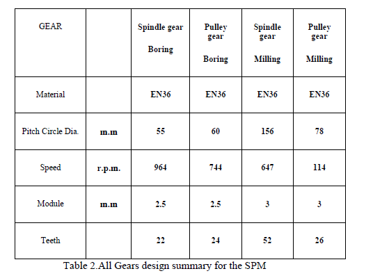 |
IV.II.DRIVE MECHANISM |
| In speed calculations for meshing gears we have to consider the output speed of the motor and the input speed given to spindle. First the drive is given to smaller pulley which is at the end of the spindle of the motor then to lager pulley which is connected to the main spindle of the gear as depicted in figure 5.1. Then the motor speed and the required speed of the spindle are different, that is the required speed of the drilling spindle is less than that of the motor speed. It needs to be reduced. By using the gear box we have to reduce the speed of the system. For which we have to consider the design of gear box. The gear box is consisting of main spindle gear, drilling gear spindle gear and idler gear spindle. The larger pulley fitted on main spindle of timing belt transmission system is also mounted on main gear spindle. Hence we have to consider diameter of the two pulleys, and calculate the speed of the pulleys. The speed of the larger pulley is equal to speed of the pulley gear G1. As shown in figure |
 |
 |
V. MANUFACTURING |
| All component of machine are manufactured and assembled considering technical issues. These parts should be sufficiently rigid and equipped with special dampers in order to minimize vibrations resulting from the operation of cutting tools. Generally, thick steel plates and cast iron are used for machine table. Cast irons have good damping character, and therefore, are used for making the machine table to reduce vibrations. Chip removal could be a huge problem in SPMs that cannot be appreciated before the machine is made. The volume of chips produced in SPMs is high and this could reduce effective machining time by half or even less when a proper chip removal mechanism is not considered. In addition, a properly designed coolant system should be used to enhance the lives of cutting tools as frequent tool changes increase machining costs. The special purpose machine shown in figure 3 and 4 |
 |
 |
VI. RESULTS & DISCUSSION |
| After successful manufacturing & testing we have get following results as shown in table 3 about machining time which is less than conventional machining processes |
 |
VII. CONCLUSION: |
| The SPM is fabricated and satisfactorily commissioned. Any saving done due to use of advanced manufacturing technique directly contributes to the net profit of the product. The following satisfactory conclusion are drawn after completion design, installation and commissioning of the SPM 1. If look at cycle time required for completing a single component, see that previously lead time required was approx 5miniuts. This is now reduced to 68 seconds. SPM saves time by loading and unloading. In case of angular drilling operation the time requires to tilt and load component was 40 sec. by using conventional drilling machine. But by using SPM the loading and unloading time of component considerably reduced. Also clamping is done by hydraulic swing cylinder. 2. Productivity has improved in both ways that is qualitative and quantitative. Special purpose machine is necessary for improving the production. 3. The SPM can complete the 400 jobs per day. Hence successfully increase the production rate up to 5 times. Also it has improved the repeatability, accuracy and less rejection, due to accurate automation. 4. SPM causes less human interaction, drastic reduction in work load through SPM which directly helps in less operator fatigue. This reduces the labor cost. Hence SPM increases the production rate, reduced production cost, and reduced labor cost which minimizes the production cost. |
References |
|