ISSN ONLINE(2319-8753)PRINT(2347-6710)
ISSN ONLINE(2319-8753)PRINT(2347-6710)
M.H. Mohamed1, M.A. Bayoumi2, Alaaeldin A. Eltawil1, A. E. Abuelezz3
|
| Related article at Pubmed, Scholar Google |
Visit for more related articles at International Journal of Innovative Research in Science, Engineering and Technology
Liquid density measurement is an important activity in many laboratories. Usually hydrometers are used to measure the density of liquids in the range from 600 kg/m3 up to 1850 kg/m3. For the purpose of metrological traceability of Hydrometers with the international density reference standards a calibration system has been designed, constructed and validated at the National Institute for Standards, NIS, Egypt. The system covers the range from 500 kg/m3 up to 2000 kg/m3. The system is automatically operated for the intended measurements and calibrations using hydrostatic weighing (Cuckow’s method). Distilled water was used as a reference liquid. Finite element analysis using (ABAQUS) software for 3D has been used to check the stress, deformation, rigidity, stability as well, to optimize the design of the system. A laser light source and two linear encoders are used to position the standard liquid surface at the hydrometer scale mark during calibration process. For accurate measurements of scale mark position, an image processing technique combined with a high resolution CCD camera for capture the reading during calibration is used. Lab VIEW program is designed to processing the reading from measurement instruments in a fully automated mode. The calibration results present an expanded uncertainty (with a coverage factor of k= 2) less than 100 ppm. The apparatus’s performance has been validated by comparing the output results of the system versus Laboratoire National de Metrologie et d’Essais “LNE” calibration certificates of 3 standard hydrometers.
Keywords |
| Liquid density, Hydrometers Calibrations, Cuckow’s method, Hydrostatic weighting system |
INTRODUCTION |
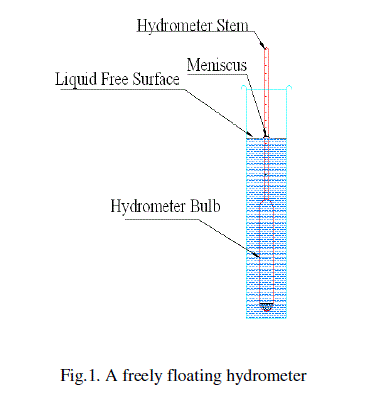
| A hydrometer is a glass instrument consisting of a bulb has a mass at its bottom and extended by a stem of small diameter, on which scale readings are marked [1] as shown in Figure 1. The operation principle operation of the hydrometer is based on the Archimedes’ principle [2] where a solid body suspended in a fluid will be buoyed up by a force equal to the weight of the fluid displaced by the submerged part of the suspended body. Apart from the simple construction of the hydrometers its calibration needs a lot of effort where two methods are normally used. The comparison method and the Cuckow’s method .The National Institute for Standards Egypt (NIS) nowadays provides a calibration service for hydrometers in the range from 600 kg/m3 up to 1850 kg/m3. The calibrated hydrometers are used as working standards to calibrate customer’s hydrometers and provide traceability to thousands of hydrometers used for density measurements in the distilling, petroleum, chemical, dairy industries. At present, NIS working standard hydrometers has been calibrated at Laboratoire National de Metrologie et d’Essais, LNE, France [3]. The NIS perform calibrations for the customers’ hydrometers by the comparison method [4] using several liquids. Mixing of these liquids to reach any point of calibration located at the hydrometer stem. The mixing process is difficult and hazard especially in the range above distilled water. In addition to the personal errors, changing in the environmental temperature during the calibration process, the meniscus which appear around the stem while the standard and under test hydrometers in freely floating in the liquid, a set of fragile, breakable standard hydrometers used to carry out the comparison method against under test hydrometers. As a consequence of the stated previous reasons, calibrations cannot be made exactly at any calibration point located at the hydrometer stem and large uncertainties of measurements are reached. A method in which only one liquid covers the whole calibration range from 500 kg/m3 to 2000 kg/m3 was developed initially at the NPL, UK [5] and suitably adapted by us in India. My colleagues, at the NPL, India, developed an open-scale hydrometer with a very small range but with a scale interval of 0.01 kg/m3 and also designed and fabricated a thermostatic bath. The bath was examined for constancy and uniformity of temperature, throughout the working space. The hydrometer is calibrated by submerging it to the required level and finding its apparent mass in the liquid. The density of the liquid is simultaneously determined with the help of the open-scale hydrometer .To get rid of these problems a fully automated hydrostatic weighing system working in the range from 500 kg/m3 up to 2000 kg/m3 is design and constructed for the calibration of hydrometers via Cuckow’s method [5-8]. |
 |
CONSTRUCTION OF THE DESIGNED HYDROMETER CALIBRATION SYSTEM |
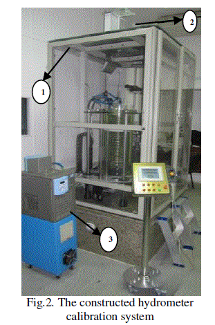
| Figure 2 shows the system that has been designed in NIS-Egypt for hydrometers calibrations. The system consists of main cabinet (1) which carries the high sensitive electronic digital balance (2) with maximum capacity 2300 g and resolution 0.1 mg. Liquid temperature controller (3) ,commercially available which is used for controlling the temperature of the water jacket with stability better than ± 0.05°K |
 |
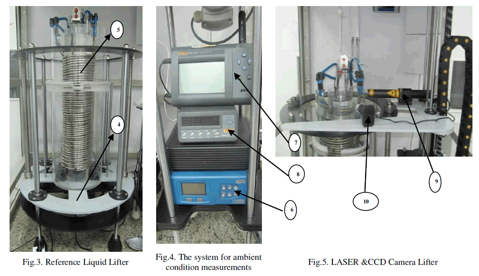
| Figure 3 shows the mechanical lifter (4) which has been designed to be rigid enough to carry the weighing cell which is consisting of two coaxial cylinders (5) having in between the jacket water. |
| Figure 4 shows a system for ambient condition measurements consists of barometer (6) with resolution 0.1 Pa to measure atmospheric pressure and thermo-hygrometer (7) with temperature resolution 0.001 ºC and relative humidity with resolution 0.01 %. This system is needed for air density calculations [9-11] at the time of weighing the hydrometer in the air, while digital temperature indicator (8) with prop sensor PT100 for measuring the temperature of the reference liquid with resolution 0.001 ºC. |
| Figure 5 shows a laser light source (9) fixed on a mechanical lifter for the movement up and down via controlled motor and two linear encoders to position the liquid surface at the calibration point and a CCD camera (10) with resolution (1600H×1200V) fixed on the same mechanical lifter of the laser light source and in the perpendicular direction. An imaging processing technique [12] is used to indicate the scale marks to be calibrated. |
 |
VALIDATION OF THE HYDROMETER CALIBRATION SYSTEM |
| The validation has been performed, by comparing the results of calibration of 3 standard hydrometers, calibrated and certified by LNE France with the calibration results, of the same hydrometers, obtained using the constructed calibration system at HCS-NIS, based on Cuckow's method. |
| a. CUCKOW’S METHOD |
| Cuckow derived a method for a calibration laboratory to determine the density ρL represented by a given scale mark on the hydrometer stem. Force balance equations are written for a hydrometer in three conditions [13]: |
| 1. When floating freely in a liquid of unknown density (ρL), |
| 2. When weighed in air and |
| 3. When weighed while immersed to the same level as case 1, but in a liquid of known density. |
| By solving the three equations simultaneously, one can derive an equation for ρL: |
 |
| When calibrating a hydrometer for use in liquids that are less dense than standard liquid, a stainless steel weight is added to sink the hydrometer. The weight is a ring of known mass and volume placed over the stem, resting on the top of the bulb. It is submerged in the standard liquid during the hydrometer calibration as equation (1). |
| Where |
| ρL : Density of the distilled water, |
| β : Volumetric thermal expansion coefficient of the glass from which the hydrometer is made, |
| TT : Temperature of the distilled water, |
| T0 : Reference temperature, |
| ρa2 : Density of the air at the time the hydrometer was weighed in air, |
| α : Calibration coefficient for the balance, |
| O2 : The balance reading for the hydrometer weighing in air, |
| D : Diameter of the hydrometer stem at the scale mark to be calibrated, |
| γL : Surface tension of the distilled water, |
| θL : Contact angle of the distilled water on the hydrometer stem, |
| g : Local acceleration due to gravity, |
| O3 : Output from the balance for the hydrostatic weighing, |
| γT : Surface tension of the distilled water , |
| θT : Contact angle of the distilled water on the hydrometer stem, |
| ms : Mass of the stainless steel weight added to sink a hydrometer, |
| Vs : Volume of the stainless steel weight, |
| βs : Volumetric thermal expansion coefficient of the stainless steel weight. |
| To calculate hydrometer corrections for a particular liquid under test. The values of A and B are the output the calibration. |
 |
| b. MEASUREMENTS AND RESULTS |
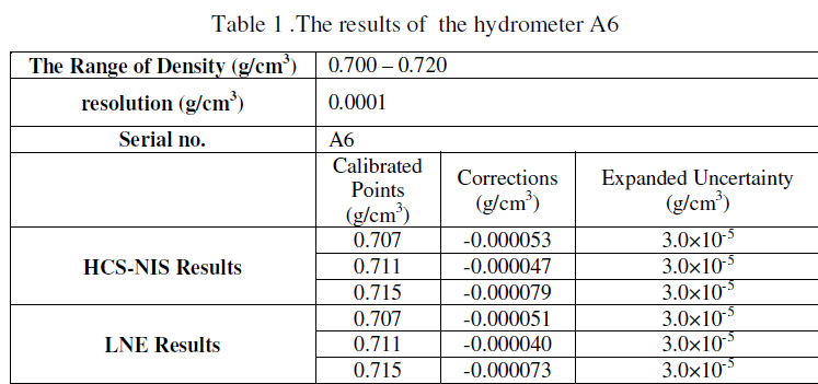
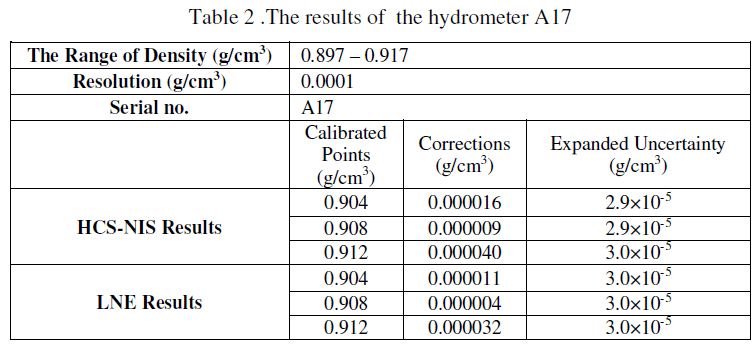
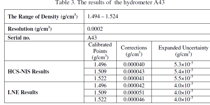
| The three standard hydrometers, A6, A17 and A43, which used for the validation process in this research, were carefully selected so that the comparison range cover different densities at the full range of the newly constructed calibration system. The obtained results as well as the certified results of LNE are given in Table 1 for density range 0.700 – 0.720 g/cm3 ( A6), in Table 2 for density range 0.897 – 0.917 g/cm3 ( A17) and in Table 3 for density range 1.494 – 1.524 g/cm3 ( A43). |
| Table 1 shows the calibration results at (0.707, 0.711 and 0.715 g/cm3) calibration points in between (LNE) and (HCSNIS) for the hydrometer A6.The maximum expanded uncertainty is 3.0×10⁻⁵ for (HCS-NIS) and it is the same for (LNE).The maximum difference in the corrections between (HCS-NIS) and (LNE) is (-0.000007 g/cm3) at calibration point (0.711 g/cm3) |
 |
| Table 2 shows the calibration results at (0.904, 0.908 and 0.912 g/cm3) calibration points in between (LNE) and (HCSNIS) for the hydrometer A17.The maximum expanded uncertainty is 3.0×10⁻⁵ for (HCS-NIS) and it is the same for (LNE).The maximum difference in corrections between (HCS-NIS) and (LNE) is (0.000008 g/cm3) at calibration point (0.912 g/cm3). |
 |
| Table 3 show the calibration results at (1.496, 1.509 and 1.522 g/cm3) calibration points in between (LNE) and (HCSNIS) for the hydrometer A43.The maximum expanded uncertainty is 5.5×10⁻⁵ for (HCS-NIS) and The maximum expanded uncertainty is 4.0×10⁻⁵ for (LNE).The maximum difference in corrections between (HCS-NIS) and (LNE) is (0.000008 g/cm3) at calibration point (1.509 g/cm3). |
 |
VALIDATION OF OBTAINED RESULTS BETWEEN (HCS-NIS) AND (LNE) |
| To validate the results obtained from the HCS-NIS, with previous results obtained from LNE have been carried out. The formula for the normalized error (En-value) was used [14] |
 |
| Where: |
| Value (Lab): is the value reported by the participating laboratory; |
| Value (Ref): is the reference value for the measured; |
| U (Lab) 95: is the uncertainty reported by the participating laboratory; |
| U (Ref) 95: is the uncertainty of the reference value |
| Results are judged as following: |
| -1≤En≤1 is satisfactory OR En> 1 or En< -1 is unsatisfactory |
| From the comparison for the range of density measured. The relative error between HCS-NIS and LNE is not more than 0.019%.By substituting in equation (5) the normalized error (En) values of the measurements are 0.17, 0.11 and 0.26 in the hydrometers A6, A17 and A43 respectively. From this comparison with calibration certificates, HCS-NIS has the validation to measure the density and calibration the hydrometers in the range from 500 kg/m3 up to 2000 kg/m3. |
CONCLUSION |
| A fully automated hydrometer calibration system at the (NIS) Egypt, has been designed, constructed and validated with the objective to be used for liquid density measurements and hydrometers calibrations in the range from 500 kg/m3 up to 2000 kg/m3.The apparatus’s performance has been validated by comparing the output results versus LNE’s calibration certificates. The calibration results present an expanded uncertainty (K=2) less than 100 ppm. |
References |
|