ISSN ONLINE(2319-8753)PRINT(2347-6710)
ISSN ONLINE(2319-8753)PRINT(2347-6710)
| C. K. Madheswaran, P S Ambily, J. K. Dattatreya, Ramesh G Scientists , CSIR-Structural Engineering Research Centre, Taramani, Chennai, India |
| Related article at Pubmed, Scholar Google |
Visit for more related articles at International Journal of Innovative Research in Science, Engineering and Technology
Geopolymer Concretes (GPCs) are a new class of concrete based on an inorganic alumino-silicate binder system compared to the hydrated calcium silicate binder system of concrete. They possess the advantages of rapid strength gain, elimination of water curing, good mechanical and durability properties and are additional ecofriendly and sustainable alternative to Ordinary Portland Cement (OPC). This paper describes experimental investigation on behaviour of reinforced GPC beams subjected to monotonic static loading. The overall dimensions of the GPC beams are 250mm x 300mm x 2200mm. The effective span of beam is 1600mm. The beams have been designed to be critical in shear as per IS:456 provisions. The specimens were produced from a mix incorporating Fly ash and GGBS, which was designed for a compressive strength of 40MPa at 28 days. The Reinforced Concrete specimens are subjected to curing at ambient temperature under wet burlap. The parameters being investigated include shear span to depth ratio (av/d =1.5 and 2.0). Experiments are conducted on 12 GPC beams and four OPCC control beams. All the beams are tested using 2000kN servo-controlled hydraulic actuator. This paper presents the results of experimental studies.
I. INTRODUCTION |
| Concrete is the most commonly used construction material. Its usage by the communities across the world is second only to water. Concrete is produced by using the ordinary Portland cement (OPC) as the binder. However, Portland cements are highly internal-energy-intensive and cause emission of green house gas, CO2 during their production. Cement production is also highly energy-intensive, after steel and aluminium. On the other hand coal burning power generation plants produce huge quantities of fly ash. Most of the fly ash is considered as waste and dumped in landfills. These concretes are found to be less durable in some of the very severe environmental conditions, therefore there is a need for development of alternate concretes. In this regard, geopolymer concrete (GPCs) can be considered as potential candidate materials. The studies on these new concretes are being carried out at SERC for more than 10 years. These new concretes utilize industrial wastes such as fly ash (FA) and GGBS to produce inorganic binder in the form of alumino-silicates. Industrial wastes, such as fly ash and GGBS , can be activated directly to produce geoplymeric binders which can be used to manufacture novel concretes are much less than Portland based conventional concretes(CCs) and CO2 ( a green house gas) generating Portland cement has been completely eliminated (Rajamane, et al., 2005a and 2005b)1,2 . |
II. REVIEW OF LITERATURE |
| Geopolymer concretes’ (GPC) are a type of inorganic polymer composites, to form a substantial element of an environmentally sustainable construction and building products industry by replacing/supplementing the conventional concretes. The term geopolymer was first introduced by Davidovits3 in 1970s to name the three-dimensional aluminosilicates material, which is a binder produced from the reaction of a source material or feedstock rich in silicon (Si) and aluminum (Al) with a concentrated alkaline solution. The source materials may be industry waste products such as fly ash, slag, red mud, rice-husk ash and silica fume may be used as feedstock for the synthesis of geopolymers. The alkaline liquids are concentrated aqueous alkali hydroxide or silicate solution, with soluble alkali metals, usually Sodium- (Na) or Potassium- (K) based. High alkaline liquids are used to induce the silicon and aluminum atoms in the source materials to dissolve and form the geopolymeric binder. Rangan (2008)9 and Rangan & Hardijito(2005) 10 |
| Wallah and Rangan 2006 discusses the development and properties of low-calcium FA based geopolymer concrete. They have described the development, the mixture proportions and the short-term properties of low-calcium FA based GPC concrete. It was concluded that Low-calcium FA-based geopolymer concrete had excellent compressive strength, suffer very little drying shrinkage and low creep, had excellent resistance to sulphate attack, and good acid resistance. The research report describes the structural behavior of geopolymer concrete beams and columns. |
III. RESEARCH SIGNIFICANCE |
| Geopolymer concrete are a class of new concretes based on an eco-friendly non-Portland cement based binder system derived from geological materials rich in silica and alumina. The extensive GPC is comparatively a new material and is still under intense R & D investigations. The structural behavior of reinforced GPCs, has been investigated to a limited extent in Australia, that to on only fly ash based; but this needs a more detailed study with various local source materials. |
| In the view of the above factors, feasibility of using conventional concreting tools and technology, and get a clear picture of the structural performance of GPCs vis-à-vis conventional cement concretes, the experimental investigations were planned and carried out. The study elucidates the development of structural grade GPC, highlight the structural behavior of reinforced GPC beams and provide a comparison with their conventional concrete counterparts. |
IV. EXPERIMENTAL INVESTIGATION |
| 4.1 Specimen details |
| The experimental program consists of casting and testing of 12 reinforced GPC and 4 OPCC control beams. Shear behavior of GPC and OPCCs beams with shear span/depth ratio of 1.5 and 2 was used. Sixteen beams are grouped in two categories with eight beams. Two OPCC beams are treated as control beams. All the beams are designed to fail in shear as per IS: 456-2000. Based on the design, 4 (four) numbers of 25mm diameter Torsteel bars are used in one layer at the bottom, and two number of 12 diameter are used in one layer at the top. |
| 4.2 Materials used |
| A concrete mix with ordinary Portland cement (OPC-53 grade) and 12.5mm and 20mm downgraded coarse aggregate are used for casting. The mix design is carried out for M30 grade of concrete. Compression tests on control and geopolymer specimen of cubes and cylinders are performed at 7 days and 28 days. |
| The GPC was obtained by mixing calculated quantities consists of Fly ash, GGBS, Fine aggregates and Coarse aggregates. FA conforming to grade 1 of IS 3812-1981 and GGBS (ground granulated blast furnace slag) conforming to IS: 12089 were used. Catalytic liquid system (CLS): It is an alkaline activator solution (AAS) for GPC. It is a combination of solutions of alkali silicates and hydroxides, besides distilled water. The role of AAS is to activate the geopolymeric source materials (containing Si and Al) such as fly ash and GGBS. The mixing of ingredients of GPCs can be carried out in mixers used for conventional cement concretes – such as pan mixer. The test specimens are designed as per the provisions of IS456-200011. A total of twelve beams with rectangular - cross section having dimensions of 250 mm x 300 mm. The effective span of the beam is 1600mm.The beams were cast for different a/d ratio (1.5 and 2.0). All the beams were reinforced with 4 numbers of 25mm diameter rods bundled at the bottom, and 2 no of 8mm diameter are provided at the top of the beam. The 8mm diameter transverse reinforcement was provided in the beam throughout the span. The beam is designed to fail in shear. The beams were divided into two series according to the shear span to depth ratio (a/d=1.5 and a/d =2.0). TMT bars of Fe 500 Grade and concrete mixes designed for characteristic strength of 40MPa were used. |
| 4.3 Mix Proportions |
| The alkaline activator solution (AAS) used in GPC mixes was a combination of sodium silicate solution (SiO2/Na2O=2.2), sodium hydroxide pellets and distilled water. The role of AAS is to dissolve Si and Al present in the reactive portion of source materials such as FA and GGBS and provide a high alkaline liquid medium for condensation polymerization reaction. The sodium hydroxide was taken in the form of flakes of approximately 3mm in size. The sodium hydroxide (NaOH) solution with required concentration was prepared by dissolving the computed amount of sodium hydroxide flakes in distilled water. |
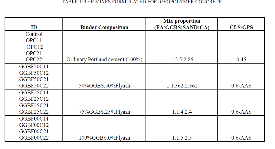
| Therefore, the formulation of the GPC mixtures was done by trial and error basis. Numerous trial mixes were cast and tested for compressive strength at end of 14 days and 28 days. The ratio of AAS to binder solids (GPS) and the compositions of GPS (FA+GGBS) were varied suitably to meet the workability and strength requirements. compare the results of tests conducted using RGPC, additional conventional concrete mixes prepared with OPC and designed as per IS 10262-2009 and ACI 211.1 guidelines. The details of the mix proportions are given in Table 1. |
 |
| 4.4 Experimental Set-up |
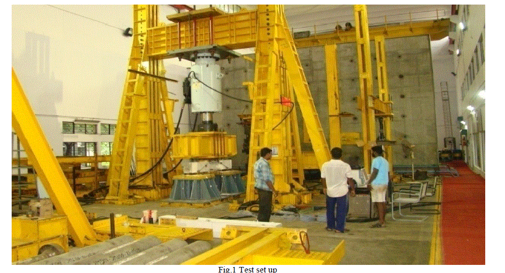
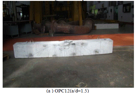
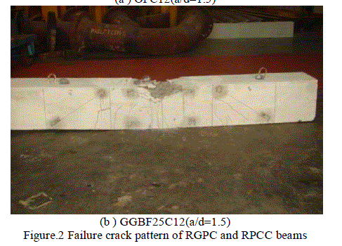
| All the specimens were white washed in order to facilitate marking of cracks. The GPC beam specimen was kept under loading frame with simply supported conditions at both ends. The beam was simply supported on the reaction blocks by a hinged plate at one end and roller plate at the other end. A 2000kN servo-controlled hydraulic actuator was used to apply the monotonic loadings. All specimens are tested using two point loading with shear span to effective depth ratio of 1.5 and 2. The displacement control mode has been conducted on both the test specimens. The tests are carried out at the FFL, CSIR-SERC. Figure 1 shows the details of the test setup. LVDTs are located at three places, one at mid span and two under load points. LVDTs are also used for each test to monitor shear strain of GPC and OPCC beams. Electrical strain gauges are used in the test, strain gauges are used on the surface of the longitudinal steel reinforcement and transverse steel. All the test specimens are tested increment loadings. After applying each increment of load, load, deflection and strain are measured simultaneously. Loading increment is continued in increments up to the failure of the specimen. The behavior of the beam was observed carefully and the crack widths were measured using a hand held microscope. All the measurements including deflections, strain values and crack widths were recorded at regular intervals of load until the beam failed. Figure 2 shows the typical crack-pattern in RPCC and RGPC beams. It was observed that flexural failure mode for RGPC and RPCC beams. |
 |
RESULTS AND DISCUSSION |
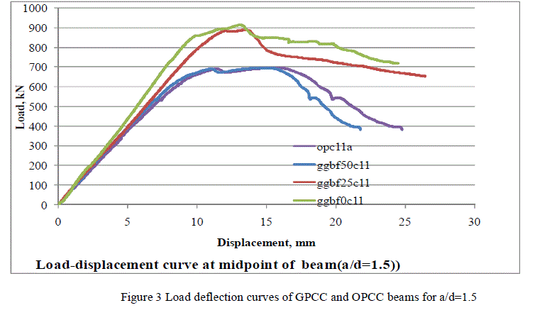
| Experimental studies on structural behaviour of reinforced GPCs and OPCC were carried out. Reinforced OPCC and GPC beams of size 250 x 300 x 2200 mm and effective span 1600 mm were tested under two points loading with shear span to depth ratios of 1.5 and 2. Two specimens each of one OPCC mix and three GPC mixes (with 0, 25% and 50% FA in the binder) were tested. The beams were designed as balanced sections in the limit state of collapse and to be critical in shear as per IS: 456 provisions. The load deflection curves for the two series of beams were obtained (Figure 3 and Figure 4). The load deflection behaviour at mid span for RPCC and RGPC beams are similar. The ultimate load carrying capacity for RGPC is 10% more then RPCC beams. The nonlinear stress-strain for concrete was used. The multilinear load-deflection curve obtained above for OPCC and GPC beam and the experimental curve are shown in Figure 5. Theoretical curve matches well with the experimental one. Theoretical analysis was carried out as per conjugate theory as presented by Antony jeyasehar (1999)5. It was found that because of the thick web, the actual shear capacity of the beams was greater than that computed using IS: 456 provisions and the beams finally failed in flexure rather than in shear. The ultimate deflection was around 26mm for OPCCs and 28mm for GPCs. Both OPCC and GPC beam failed in flexural mode near at the loading span. All the specimens exhibited similar flexural failure modes, crushing of concrete slab in the central bending portion. Figure 2 show the crack pattern was essentially dominated by flexural cracks, which spread throughout the width of slab. The failure of the specimen was top crushing and compression of concrete for both GPC and OPCC in loading span. Figure 5 shows the shear strain responses of OPCC beams at various locations. Figure 6 and Figure 7 shows the shear strain responses of OPC beams and GPC beams. The Shear strain responses of GPC beams are also similar to OPC beams. |
| The ultimate strain is computed using the equation suggested by Corley (1966) which considered the effect of confinement of concrete. |
| The ultimate strain is computed using the equation suggested by Corley (1966) is found to be good agreement with the experimental measured strain. |
 |
 |
 |
VI. COMPARISON OF TEST RESULTS AND THEORETICALLY COMMUTED RESULTS |
| 6.1 Flexural Moment Capacity |
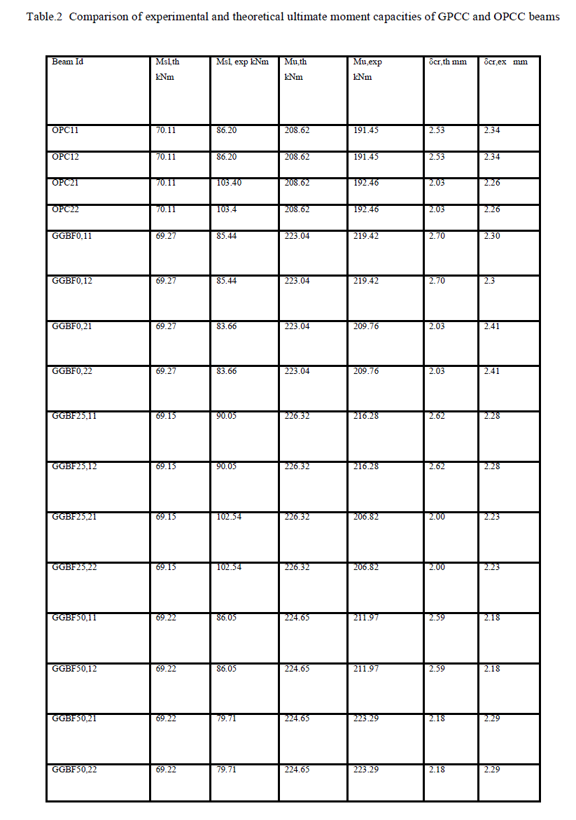
| Table 2 compares the predicted values of flexural moment capacity at cracking and ultimate load for RPCC beams and RGPC beams. The predicted values were obtained by theoretical analysis using the transformed section method and strain compatibility method specified in the codes of practice for reinforced cement concrete. The flexural strength required for the computation of cracking moment was obtained from the corresponding cube strength using the formulae recommended in the codes of practice . The comparison with experimental values indicates lack of good agreement, especially in case of RPCC beams and GGB series. |
| 6.2 Beam Deflections |
| The mid-span deflection was predicted at cracking, yielding moment and ultimate stages. In the first crack stage, the gross moment of inertia was used and the deflection was calculated using the expression given for the maximum elastic deflection of a simply supported homogeneous beam subjected to two point loading as, |
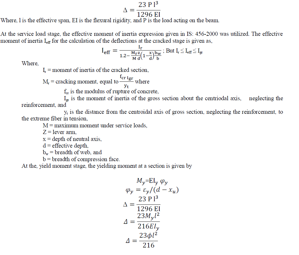 |
| A similar approach was used for the deflection at the peak load. Comparison between the test load and the corresponding predicted deflections show fairly good agreement with the actual measurements. The agreement may be poor due to reliance of the approach on sectional analysis and ignoring the contribution of shear deflection besides extraneous deflection due to support settlement and load transfer yoke. There is a need for improved computational methods and more accurate measurement of deflections. |
 |
VII.CONCLUSIONS |
| Experimental studies on the behavior of reinforced GPC and OPCC beams subjected to monotonic static loading were carried out. The parameters investigated include shear span to depth ratios of (a/d=1.5 and 2) and comparison of behavior of reinforced GPC with OPCC beams. Three GPC mixes (0%, 25%, 50% FA) with different proportions of AAS (Consisting of NaoH and Na2Sio3) and one OPCC mix were considered for the study. |
| Based on the experimental and analytical investigations carried out on the behavior of GPC and OPCC beams, it was concluded that |
| 1. The load deflection characteristics at mid span of the Reinforced GPC and OPCC control beams were found to be almost similar. Also, the GPC beams showed slightly more deflections at the same load than the OPCC beams. |
| 2. The ultimate moment carrying capacity of test beams was calculated from the first principle using strain compatibility methods and provisions of IS:456-2000. The nonlinear stress-strain relations for concrete have made it possible to reach the ultimate load and determine the entire load-deflection curves. Good correlation was found between the test and predicted values. The values of maximum curvature for the GPC beams and OPCC beams were same, but reinforced GPC beams had more curvatures. The theory of conventional reinforced concrete is applied to geopolymer concrete also. |
| 3. The crack patterns observed for both a/d ratio of 1.5 and 2 GPC beams found to be similar to the OPCCs beams. The failure pattern of all the beam specimens was found to be similar. At the early load stages, flexural cracks appeared in the central portion and gradually spread towards supports. All the beams failed in flexural mode by yielding of reinforcement and crushing of concrete in the compression mode. |
| 4. There was a good agreement between experimental and analytically predicted values of deflection, indicating the applicability of analytical tools of OPC to GPC. |
| 5. The geopolymer concrete were found to be performing adequately as structural components and could be considered as a potential candidate material for replacing OPCC. |
| 6. Geopolymer concrete is more environmental friendly and economical and has the potential to replace ordinary cement concrete in many applications such as precast units. |
ACKNOWLEDGEMENTS |
| The paper is being published with the kind permission of Director, CSIR-Structural Engineering Research Centre, Chennai. The cooperation and guidance received from the technical staff of advanced materials laboratory of CSIRSERC is gratefully acknowledged. |
References |
|