International Journal of Innovative Research in Science, Engineering and Technology
ISSN ONLINE(2319-8753)PRINT(2347-6710)
ISSN ONLINE(2319-8753)PRINT(2347-6710)
| Rajesh Kumar Ahuja and Amit Kumar Department of Electrical Engineering, YMCA University of Science & Technology, Faridabad, India |
| Related article at Pubmed, Scholar Google |
Visit for more related articles at International Journal of Innovative Research in Science, Engineering and Technology
A Nine-Level Diode Clamped Inverter with Sinusoidal PWM technique is presented in this paper. Three Phase inverter is studied and simulated in MATLAB/SIMULNK. In this paper the inverter is controled with the Level Shifted scheme of Sinusoidal PWM i.e. Phase Diosposition (PD), Phase Opposition Displacement (POD) and Alternative Phase Opposition Displacement (APOD). The inverter is simulated for R-L load and THD for output waveforms is observed for differnt controlling schemes. The THD for the output waveforms is observed and the the technique with least THD is seleted for furhter simulations
Keywords |
| Diode Clamped, Multi-Level Inverters, PD, POD, APOD, THD and NPC. |
INTRODUCTION |
| In recent years the Multi-Level Invertres are very popular for Industrial and powers system applications due to their advantages on Two-level inverters i.e. High Power rating, Low Harmonics so they give the higher effiency. The different topologies of Multi-Level Inverters are Neutral-point clamped (NPC) or Diode Clamped (DC) inverter, Flying capacitor inverter and Cascade inverter. As the level increases, NPC require more clamping diodes so the control of real power flow becomes very difficult. In flying capacitor inverter as the level increases, number of storage capacitors also increases hence they becomes bulky and costly; there are more switching losses in this topology. |
| The cascaded multilevel inverters have more advantages than other topologies, because it does not require any balancing capacitors and diodes. Cascaded inverters need separate DC sources for each H-Bridge, so there is no voltage balancing problem, but isolated DC sources are not readily available, this is the main drawback of this topology. In this paper Diode Clamped Inverter is studied for different control schemes and at different values of the Loads (R-L). |
DIODE CLAMPED INVERTERS |
| The first invention in multilevel converters was the so-called neutral point clamped inverter. It was initially proposed as a three level inverter. |
| The main advantages and disadvantages of this topology are: |
| • High efficiency for the fundamental switching frequency. |
| • The capacitors can be pre-charged together at the desired voltage level. |
| • The capacitance requirement of the inverter is minimized due to all phases sharing a common DC link. |
SINUSOIDAL PWM |
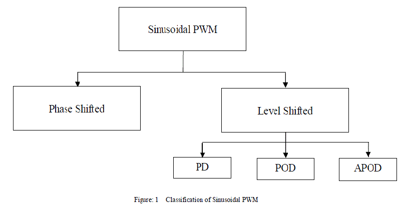
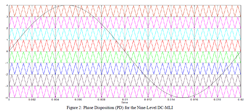
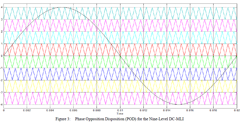
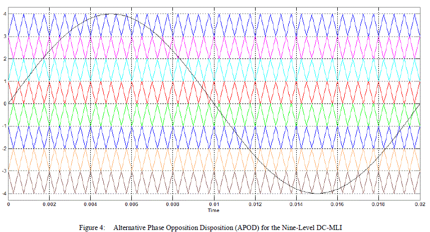
| Control techniques for multilevel inverters are based on fundamental and high switching frequency. SPWM, SVPWM and SHE-PWM techniques are mostly used. The SPWM scheme is widely used due to many advantages i.e. simple implementation, low harmonic outputs compares to other schemes, and less switching losses. In SPWM scheme, a high frequency triangular signal is compared with a low frequency modulating signal to generate the control signals. The SPWM is further classified as Phase Diosposition (PD), Phase Opposition Displacement (POD) and Alternative Phase Opposition Displacement (APOD) and is shown in fig.1 |
| Figures 2,3 and 4 shows these disposition techniques. Each of these variations has particular harmonic benefits. |
 |
 |
SIMULATION OF NINE-LEVEL INVERTER |
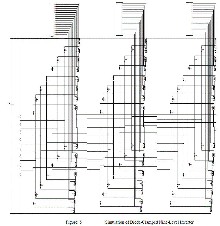
| The simulation of Nine-Level Inverter is shown in Figure: 5 The inverter is realised by Diode- Clamped Topology. |
 |
SIMULATION RESULTS |
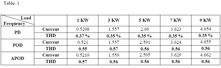
| The topology presented in this paper employs PD, POD and APOD techniques of SPWM technique. A Nine-Level Inverter is controlled with the different schemes. The THD for output waveforms have been observed and analysed for each control scheme. |
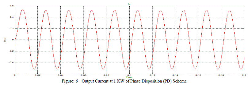
A. Results of Nine –Level Inverter using Phase Diosposition Scheme of SPWM |
| Nine-level inverter is simulated using Phase Diosposition scheme and operated at different values of R-L load at 0.8 p.f. Output current, output voltage and Current THD is observed and shown in figures given below. |
 |
B. Results of Nine –Level Inverter using Phase Opposition Diosposition Scheme of SPWM |
| Nine-level inverter is simulated using Phase Opposition Diosposition scheme and operated at different values of R-L load at 0.8 p.f. Output current, output voltage and Current THD is observed and shown in figures given below. |
 |
C. Results of Nine –Level Inverter using Phase Alternative Opposition Diosposition Scheme of SPWM |
| Nine-level inverter is simulated using Phase Alternative Opposition Diosposition scheme and operated at different values of R-L load at 0.8 p.f. Output current, output voltage and Current THD is observed and shown in figures given below. |
 |
 |
CONCLUSION |
| Nine-Level Inverter is simulated using MATLAB. THD of current at different values of loads is observed using different Control Schemes of Sinusoidal PWM i.e. Phase Diosposition (PD), Phase Opposition Displacement (POD) and Alternative Phase Opposition Displacement (APOD). |
| THDs are analysed and summerized in Table 1. It is cleared from summery that THD for output current is Minimum for the PD scheme and maximum for APOD. |
| So it is clear from the simlation that the Phase Diosposition (PD) scheme is best suited for Diode-Clamped Multi-Level Inverter because this scheme produces least harmonis as compared to another two schemes hence the effenciency increases. |
References |
|