Research & Reviews: Journal of Material Sciences
ISSN:2321-6212
ISSN:2321-6212
Nuclear Chemistry, Department of Chemistry, Chalmers University of Technology, Kemivägen 4, 412 96, Göteborg, Sweden
Received Date: 01/09/2017; Accepted Date: 03/10/2017; Published Date: 10/10/2017
DOI: 10.4172/2321-6212.1000196
Visit for more related articles at Research & Reviews: Journal of Material Sciences
Uranium nitride (UN) is a possible accident tolerant fuel candidate for light water reactors. Apart from advantages in high metal density and high thermal conductivity, it suffers from low stability in water. We have suggested exploiting metal inclusions to enhance its stability in water by forming a protective layer. A uranium nitride doped with chromium (Cr 2.7 wt%), nickel (Ni 2.8 wt%) or aluminum (Al 1.5 wt%) was prepared by internal sol gel and carbothermal reduction. An electron dispersive spectroscopy revealed a homogeneous distribution of metals in all sol-gel products. The carbothermal reduction was performed in the N2+5%H2 mixture at 1500°C for 6 hours. X-ray diffraction confirmed UN phase formation in the samples. Pellets were manufactured by sintering in argon at 1800°C for 6 hours. During the sintering, a majority of the chromium evaporated from a surface, nickel moved towards the grain boundaries and aluminum formed an agglomerate on the rim of a pellet. Finally, the pellets were boiled in water at normal pressure. A reference pellet of pure UN utterly collapsed after 2 hours of boiling. Both nickel and aluminum doped pellets disintegrated within a couple of minutes. The chromium doped pellet did not collapse during 5 hours of boiling. This indicated a clear improvement in corrosion resistance of the uranium nitride based material.
Before 2011 Accident Tolerant Fuels (ATFs) research mainly focused on increasing burnup, power density, and fuel reliability. After the Fukushima Daiichi event in 2011 a more extensive investigation of ATFs was triggered and attention was targeted on troubleshooting the issue with an accelerated hydrogen production that occurs during the loss of cooling in the core. In relation to that, a new group of fuels and claddings was defined [1]. The novel types of materials for fuel assembly should withstand the loss of active cooling in the core for a longer time period [2] and should also have an improved performance during the normal operating conditions, together with the low operating cost, to be economically viable [3]. A list of prospective candidates both for fuels and claddings was suggested: fully ceramic microencapsuled fuels (FCM) [3] that offer excellent fission product retention for the cost of low uranium density; uranium-molybdenum metallic fuels (U-10% Mo) with very high thermal conductivity and fissile density but considerably low melting temperature; uranium-silicide fuels (U3Si2) with high enough thermal conductivity, fissile density and minimal parasitic neutron absorption [2] and uranium-nitride fuels (UN) which possess high thermal conductivity, high fissile density, and high melting point [3], but it decomposes in hot water or steam [4]. Advanced zirconium cladding, silicon carbide cladding (SiC), advanced steel cladding and molybdenum cladding are on the list of accident tolerant claddings [2].
UN is one possible accident tolerant fuel, mostly due to its high thermal conductivity (15,8 W/m.K at 1000 K), which moreover rises with temperature [5,6], unlike UO2. The higher thermal conductivity enables operation at lower temperatures [4], which guarantees less heat is retained in the fuel elements. Therefore a migration of fission products and actinides decreases. Thus, high thermal conductivity favorably affects the swelling issue [7] and allows the price of fuel assembly production to be lower due to a possibility to utilize larger fuel elements [4]. UN also has a high melting point 2830-2850°C [8] and higher (than UO2) fissile atom density 13.5 g/cm3, which means higher power density. The higher density of UN allows the space in a core to be used effectively, since UN occupies about 30% less volume compared to UO2 [9].
However, UN is not stable in hot water, where it hydrolyzes and converts into oxide (in a solid form). Such processes can be seen from the corrosion perspective. In order to improve the corrosion resistivity of UN, the possibility of doping the UN matrix with a suitable protective component e.g. chromium (III) oxide (Chromia), aluminum (III) oxide (Alumina) or nickel oxide in concentration less than 10 vol.% was suggested in order to keep the economic benefit and not to dilute uranium in the fuel. When selecting suitable dopands, the value of cross section for neutron absorption was taken into account. The incorporation of Chromia was already tried by Areva Inc. [10] for other reasons, to enhance grain growth during the sintering of uranium dioxide pellets, to reduce fission gas production, plus to lock cesium in the fuel matrix [3]. Aluminum was suggested as a coating to reduce corrosion [3] and nickel was chosen for its good corrosion resistance in air [11], despite nickel nitride decomposing at higher temperatures [12].
In this work, an internal sol-gel and carbothermal reduction route were chosen to fabricate a uranium nitride material with chromium, nickel or aluminum inclusions. The possibility to form homogeneous materials, or even solid solutions, during the carbothermal reduction motivated working with solution rather than powders. The materials produced were then sintered and their behavior was tested in boiling water at normal pressure.
Corrosion Resistance
Instability of UN in water can be investigated from a corrosion perspective. Under certain conditions, such as redox potential, pH, oxygen concentration, temperature and pressure, some materials (e.g. chromium (III) oxide) are more stable in water than other materials (e.g. chromium). This fact is taken advantage of in manufacturing corrosion resistant alloys (e.g. stainless steels), which have a protective layer of chromium (III) oxide on the surface of an iron alloy [13]. The use of multiple protective layers was suggested by KAERI´s LWR fuel technology group. They decided to test minor alloying elements (Nb, Mo, Zr, Si) to protect UN from violent reaction with water [14].
A prediction of corrosion, or passivity (a protective layer is formed), or immunity (no corrosion) is commonly visualized in the form of Pourbaix diagrams, where the electrochemical potential is plotted against pH. A first system of interest in this study is a chromium in pure water at 300°C. Chromium in the form of chromium (III) oxide Cr2O3 is a common anti-corrosion additive. It is mostly used in steels with iron and nickel, where it forms a protective layer if more than 5 wt% of the alloy is formed by Cr [15]. Cr2O3 is stable in water at a wide range of pH and low content of dissolved oxygen (Figure 1). A dotted line in Figure 1 indicates a neutral pH at 300°C. In a reactor core the level of dissolved oxygen in water is kept below 5 ppb by hydrogen injections [16] to suppress radiolysis, and the electrochemical potential of water was measured to be between -150 mV to -100 mV using a standard hydrogen electrode (SHE) [17]. Therefore, a uniform protective layer or multiple layers of Cr2O3 would prevent UN from corrosion under operating conditions in the core.

Figure 1: A Pourbaix diagram of chromium species at 300°C. A vertical dotted line corresponds to a neutral pH at 300°C [13].
Chromium nitride CrN is expected to have a high corrosion resistance [18]. The same effect of a protective layer could be formed by aluminum (III) oxide Al2O3 in a pH range from 5 to 7.5, but Al2O3 transforms into [AlO2]- at higher pH [19]. Other metals, such as silicon, titanium, tantalum, niobium or nickel can form a protective oxide layer [15].
Internal Sol Gel Process
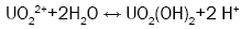
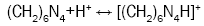
The sol-gel process was originally designed for the purpose of producing a coated particle fuel for High Temperature Gas Cooled Reactors (HTGRs) and internal gelation process known as KEMA process was developed in KEMA laboratories in the Netherlands [20]. An estimated chemical form of metals after gelation is a oxy-hydroxide UO2(OH)2 or hydrated oxide UO3xH2O [21]. The internal sol-gel method is based on the precipitation of metals, which is governed by a pH shift in the solution towards alkaline. This shift is controlled by a change in the temperature, which causes subsequent chemical decomposition of a gelating agent hexamethylenetetramine (HMTA), resulting in ammonia formation. This transformation optimally takes place immediately after the droplet of a cooled sol (2-7°C) comes into contact with a heated medium, e.g. silicon oil (60-90°C). An undesired pregelation in the cooled sol can occur as well. Four principal reactions are involved in the gelation process: decomplexation of urea (reaction 1), hydrolysis of uranyl ions (reaction 2), HMTA protonation (reaction 3), HMTA decomposition (reaction 4).
 (1)
(1)
 (2)
(2)
 (3)
(3)
 (4)
(4)
Since the precipitate is a hydrolysis product - oxide/hydroxide, in the next step a carbothermal reduction (reaction 5 and 6) route is needed to convert oxide to nitride [22]. For this reason, carbon (typically carbon black) must be blended with the sol before the gelation step. In order to mix hydroscopic carbon thoroughly with an aqueous solution an addition of a surfactant is necessary [23] and in general it is often hard to prepare a gel with evenly distributed carbon particles. Improvements in use of carbon black without dispersing agent were done by e.g. ref. [24].
UO3+0.5 C (s) → UO2+0.5 CO2 (g) (5)
UO2+2 C (s) +0.5 N2 → UN+2 CO (g) (6)
Solid Solution Formation
For a production of the doped materials, it would be ideal to form a solid solution between metal nitrides and thought ensure as best homogeneity in the material as possible. A solid solution is defined as a one phase system of a solute and a solvent, in which the crystal structure of the solvent is unchanged [25]. Whether the solid solution between two elements will form or not can be estimated by Hume-Rothery Rules [26]. These rules take into account four parameters: 1. a difference in atomic radius, which must be less than 15%; 2. a similar electronegativity of both elements; 3. an identical valence; 4. a possibility to crystalize in the same crystal system. These parameters for U, Cr, Ni and Al are listed in Table 1. The atomic radius difference between uranium and other elements is always more than 15%. The Pauling electronegativity differs significantly among the elements and the same valence is fulfilled only for U and Cr. Nevertheless uranium, chromium, and aluminum mononitride, as well as metallic nickel have the same fcc NaCl structure.
Table 1. The Hume-Rothery Rules applied to uranium-chromium, uranium-nickel and uranium-aluminum systems.
| Element | r [Å] | r difference [%]* [27] | Valence [27] | X | Crystal structure |
|---|---|---|---|---|---|
| Cr | 2.33 | 18 | 4s23d4 | 1.66 | CrN fcc NaCl [28] |
| Al | 2.39 | 16 | 3s23p1 | 1.91 | AlN fcc NaCl, or Cp [29] |
| Ni | 2.19 | 23 | 4s2sd8 | 1.61 | Ni3N cP, Ni fcc NaCl [30] |
| U | 2.83 | 0 | 7s25f4 | 1.38 | UN fcc NaCl [31] |
r atomic radius, cP primitive cubic, X Pauling electronegativity
*(r(solvent) - r(solute))/r(solvent). Based on the Hume-Rothery Rules, it is unlikely that a solid solution would form between selected elements. Moreover, in the uranium–chromium–nitrogen system an orthorombic ternary phase U2CrN3 should form at 1200- 1600°C rather than UCrN [32].
Fabrication of Spheres by Internal Gelation
The internal sol-gel process was adjusted to suit our requirements [33]. A starting material - Uranyl Nitrate Hexahydrate (UNH) was produced from metallic uranium (uranium metal rod) by dissolving it in concentrated nitric acid. A preparation of Acid Deficient Uranyl Nitrate (ADUN, NO3-/UO22+<2) [34], which requires either use of sub-stoichiometric nitric acid or two sources of uranium, was eliminated for practical reasons. Crystals of uranyl nitrate hexahydrate (UNH) UO2(NO3)2.6H2O were collected from a mother liquor, washed in water, air dried and used for a feed solution preparation. Such modification would allow a direct connection to the current reprocessing process of a spent nuclear fuel, which is also based on dissolving the fuel in the nitric acid and forming uranyl nitrate. Nevertheless, when NO3 -/UO22+=2 a higher amount of HMTA is needed for the precipitation to occur. HMTA amount is however based on pH and is therefore versatile, since the pH of a sol can be adjusted with e.g. ammonia solution [35]. A presence of a high amount of NO3 - anions in the sol has a downside in reduced solubility of UO2 +, which results in lower final metal concentration [36]. The solubility limit of uranyl nitrate monohydrate at 5.5°C in water is 50.55 wt% [37], which corresponds to 2.9 M.
A feed solution was prepared according to the desired composition by dissolving UO2(NO3)2.6H2O and Cr(NO3)3.9H2O (chromium (III) nitrate nonahydrate, Lancaster Synthesis, 98+%), or Ni(NO3)2.6H2O (nickel (II) nitrate hexahydrate, Merck, 99%, pro analysis), or Al(NO3)3.9H2O (aluminum (III) nitrate nonahydrate, Merck, 98.5%, pro analysis) in water together with Triton X-100 (non-ionic surfactant, Sigma Aldrich, laboratory grade). Carbon Nanopowder (CNP) (Graphitized, Supelco, <200 nm size, 99.95%) was added in a molar ratio between carbon and metals (M) C/M=2.5 (Table 2). Ultrasonication was applied for better dispersion of carbon. The sol was then placed in a cooling bath (2-7°C) with constant stirring. Urea (Sigma Aldrich, 99%, pearls) in solid form was added to the cooled solution in a molar ratio UREA/M=1.2-1.3. After a complete dissolution of urea, hexamethylentetramin (HMTA) (Sigma Aldrich, 99%) in solid form was added to the sol in a molar ratio HMTA/M=1.6-1.7. Approx. 30 minutes after the addition of HMTA, the sol was transferred into a column filled with heated silicon oil (Silicon oil V 1000, Rhodorsil, cSt) (60-90°C). The droplets of sol gelated before they reached the bottom of the column. The gelled spheres were then collected from the column and repeatedly rinsed (2-3 times for 10-15 min) with petroleum ether (Sigma Aldrich, puriss, high boiling) to remove the silicon oil. Aging was performed in ammonia solution (Merck KGaA, 25%) for 15 minutes to complete gelation and to remove the byproducts, such as ammonium nitrate and formaldehyde [38]. The spheres were then air dried and oxidized overnight at an ambient temperature and stored, or washed again in petroleum ether if persistent silicon oil remained, which was visualized by leaked silicon oil drops under the spheres. The average shape and the diameter of the spheres were examined by SEM Hitachi TM 3000 microscope. The carbon and metal distribution, both on the surface and in the bulk of air dried spheres, was verified with Energy Dispersive X-ray Spectroscopy (EDS) and Quantax 70 software.
Table 2. The composition of the sols for the internal sol-gel process of uranium-chromium, uranium-nickel and uranium-aluminum materials production.
| x=Cr | x=Ni | x=Al | |
|---|---|---|---|
| Concentration of uranium [mol/L] | 1.5 | 1.51 | 1.51 |
| Concentration of x [mol/L] | 0.19 | 0.18 | 0.22 |
| Uranium wt% | 97.3 | 97.2 | 98.5 |
| x wt% | 2.7 | 2.8 | 1.5 |
| x* vol% | 9.5 | 7.0 | 8.9 |
| x mol% | 11.3 | 10.6 | 11.9 |
| Molar ratio carbon/uranium | 2.49 | 2.48 | 2.50 |
| Molar ratio carbon/M** | 2.21 | 2.22 | 2.18 |
| Molar ratio HMTA/M** | 1.69 | 1.70 | 1.66 |
| Molar ratio HMTA/H+ | 0.80 | 0.85 | 0.78 |
| Molar ratio UREA/M* | 1.28 | 1.29 | 1.25 |
*vol% calculated for Cr2O3, NiO and Al2O3, **M=uranium+metal (x)
Nitridation of the Product by Carbothermal Reduction
Air dried spheres were placed in a molybdenum crucible. The carbothermal reduction was performed in a custom made high temperature graphite heated furnace Thermal Technology LLC: Model 1000 in a mixture of nitrogen and hydrogen (95% N2+5%H2) with a gas flow of 1 L/min at 1500°C for 6 hours. The nitrogen mixture was used during a heating step and for reaction, while cooling was performed in argon to prevent sesquinitride formation. The heating and cooling ramp was 20°C/min. Product after the thermal treatment was examined by SEM/EDS in order to evaluate metal distribution and the microstructure of the spheres. A small amount of the produced spheres were ground into a fine powder to prepare samples for XRD measurement.
Pelletization of Nitrided Product
Nitrided spheres were either directly pressed into a form of green pellet or milled into fine powder and then pressed. The green pellet was sintered on a tungsten plate in argon with a flow of 1 L/min at 1800°C for 6 hours. The mass and the dimensions of the final pellet were than measured in order to estimate density.
Dissolution in Boiling Water at Atmospheric Pressure
A pellet was put on a glass holder and hung roughly in the middle of a 0.5 L glass beaker containing 400 ml of deionized water. The water in the beaker was constantly stirred and heated to ensure as equal a temperature in the entire volume as possible. During the boiling, a watch glass was placed on top of the beaker to minimize the water vapor loss. A tentative pH test was done with a pH stick; both vapor and liquid were checked to see if ammonia was formed from nitride during boiling.
A pure uranium nitride pellet with 75.6% theoretical density (TD), and estimated composition UN0,78C0,22 based on Vegard’s rule, was used as a reference sample. This pellet collapsed and formed a suspension after 2 hours of boiling. A bubble formation from the pellet surface was observed, signaling either degassing of pores or gaseous ammonia formation. Nevertheless, all pH measurements were neutral.
Characterization of Air Dried Spheres by SEM/EDS
U/Cr: Spheres of a soft dark green gel were formed within 1 minute in the presence of 90°C silicon oil (Figure 2). The spheres were not evenly colored (dark spots of low electron reflecting material - carbon layers versus white speckles of highly reflecting material - uranium), which indicated a patchy distribution of carbon in the material (Figure 3 right). Contrary to the carbon distribution, both metals were homogeneously dispersed in the material (Figure 3 left). During the aging step, however, significant losses of carbon were registered. Graphite particles were washed out into ammonia solution. Finally, the gelled beads did not utterly solidify and remained soft after the aging step.

Figure 2: The SEM image of a single air dried sphere prepared from uranium and chromium nitrate.

Figure 3: The SEM/EDS mapping of uranium and chromium (left) and carbon (right) distribution on the surface of an air dried sphere prepared from uranium and chromium nitrate.
U/Ni: Spheres of a soft black gel were formed over approximately 1 minute of presence in the 60°C silicon oil. All spheres were equally black in color, which showed an even distribution of carbon in the material. During the aging step no significant losses of carbon into ammonia solution were observed. The initial soft gel hardened significantly after the washing in petroleum ether and the aging in ammonia solution, which meant an incomplete gelation in the previous step. The distribution of both metals in the material was homogeneous (Figure 4). The spheres had a tendency to splice together, and after they were air dried silicon oil leaked out. A remarkable amount of silicon oil was detected on the surface by SEM/EDS, meaning that the washing step was not sufficient.

Figure 4: SEM/EDS mapping of the distribution of U and Ni within the air dried sphere.
U/Al: Spheres of a soft black gel were formed within 1 minute in the presence of 90°C silicon oil (Figure 5). During the aging step, significant losses of carbon were registered, as carbon was washed out into ammonia solution. The surface of the spheres was covered with the carbon residues (Figure 6 right). Contrary to carbon distribution, both metals were homogeneously distributed throughout the material (Figure 6 left). The beads remained soft and glued together after washing and aging. Remains of silicon oil were detected on the surface of spheres.

Figure 5: The SEM image of a single air dried sphere prepared from uranium and aluminum nitrate.

Figure 6: SEM/EDS mapping of uranium and aluminum (left) and carbon (right) distribution on the surface of an air dried sphere prepared from uranium and aluminum nitrate.
Characterization of Nitrided Material by SEM/EDS and XRD
U/Cr: Highly porous spheres were produced after the carbothermal reduction. The lower part of the beads turned darker and the upper part became a light grey color. Most of the spheres cracked during the thermal treatment (Figure 7) and the mass loss of sample was about 70% (determined by weighing up the sample mass before and after the thermal treatment). Chromium redistributed within the material and formed spots of higher concentration (Figure 8). The presence of chromium was confirmed by EDS (Figure 9). The XRD pattern revealed a multiple phase system in the sample, corresponding to uranium nitride, uranium oxide, chromium oxide and chromium nitride (Figure 10).

Figure 7: SEM image of a sphere containing uranium and chromium after nitridation.

Figure 8: SEM/EDS mapping of the distribution of U and Cr inside a nitrided sphere.

Figure 9: The EDS spectrum of inside the sphere of a U/Cr sample after carbothermal reduction.

Figure 10: The XRD patterns of a U/Cr sample after carbothermal reduction. The major phase corresponds to nitrides (top), the second phase corresponds to oxides (bottom).
U/Ni: Also in the case of nickel inclusions, highly porous spheres (Figure 11) were produced after the carbothermal reduction. The lower part of the beads turned darker and the upper part became a light grey color. Most of the spheres cracked, but retained a spherical shape during the thermal treatment. The mass loss was about 70%. Nickel remained homogeneously distributed and in a detectable amount (Figure 11 right). The XRD pattern revealed a single phase system corresponding to uranium nitride (Figure 12).

Figure 11: SEM image of a sphere containing uranium and nickel after nitridation (left). SEM/EDS mapping of the distribution of U and Ni inside a nitrided sphere (right).

Figure 12: XRD pattern of U/Ni sample after carbothermal reduction; the phase corresponds to UN.
U/Al: Aluminum doped spheres consisted of a fine thin structure after thermal treatment. Al partly segregated from uranium (Figure 13). The XRD pattern revealed a multiple phase system in the sample corresponding to UN, AlN and Al2O3 phases (Figure 14).

Figure 13: SEM/EDS mapping of a sphere containing uranium and aluminum after nitridation.

Figure 14: Consists of two XRD patterns which overlap each other patterns of U/Al sample after carbothermal reduction; the phases correspond to uranium nitride and Aluminum (III) oxide and aluminum (III) nitride.
Pelletization Process and Characterization of Pellets by SEM/EDS and XRD
U/Cr: Roughly 1 gram of thermally treated microspheres were used to make a pellet. Microspheres were put into a pressing die and pressed with 0.9 GPa for a couple of seconds. The green pellet of 9.03 mm in diameter was then placed onto a tungsten plate and sintered in a graphite heated furnace. After the sintering, the pellet color turned a light grey, and the diameter scaled down to 8.49 mm. The top surface of the pellet was less porous than the bottom (Figure 15) and the observed high porosity correlated well with the low calculated density. During the sintering an interaction between the pellet and tungsten plate occurred (Figure 16) and resulted in covering a certain part of the pellet bottom with tungsten, which was confirmed by EDS (Figure 17). A strong unidentified peak that could correspond to molybdenum based on its keV value was also measured on the top surface of the pellet by EDS. However the identification of this peak remained open to interpretation. Both XRD and SEM/EDS were then measured on both sides of the pellet. Based on the EDS spectrum a major portion of chromium left the surface during sintering at 1800°C (Figure 18). Therefore, a shorter sintering process, which is feasible at lower temperatures, would be preferred in future experiments e.g. spark plasma sintering [39]. The density calculated from the weight and the dimensions is shown in Table 3. The oxide phases for both uranium and chromium were detected on both sides of the pellet surface (Figure 19). The partial oxidation of the sample might have originated from the manipulation with the sample in the box (weighing, pressing, SEM, XRD) where the oxygen level fluctuated between 230 ppm and a couple of percent.

Figure 15: A SEM image of the top (left) and bottom (right) surface of the U/Cr pellet after sintering in argon.

Figure 16: A photo of U/Cr pellet after sintering in argon. From left to right the top surface and the bottom surface.

Figure 17: A SEM image of the U/Cr pellet bottom showing an interaction with tungsten from the tungsten plate.

Figure 18: The EDS spectrum of the top of the U/Cr pellet after sintering in argon, showing a nearly complete absence of chromium on the surface and an unidentified peak.

Figure 19: XRD pattern of the U/Cr pellet after sintering in Argon. Three phases corresponding to UO2, CrO2 and UN were detected on the surface.
Table 3: Calculated densities and shrinkage of pellets U/Cr, U/Ni, and U/Al.
U/Cr |
TD of UN | 40% | TD of UO2 | 59% | shrinkage | 6% |
| U/Ni | TD of UN | 57% | TD of UO2 | 138% | shrinkage | 23% |
| U/Al | TD of UN | 51% | TD of UO2 | 75% | shrinkage | 18% |
U/Ni: Roughly 0.5 gram of thermally treated microspheres were milled into a fine powder, put in a pressing die and pressed at 1.2 GPa for 2 minutes. The green pellet with diameter of 9.23 mm was then placed onto a tungsten plate and sintered in a graphite heated furnace. After the sintering the pellet color turned grey (Figure 20) and the diameter scaled down to 7.16 mm. The 23% shrinkage confirmed that nickel acts as a sintering agent [40]. XRD and SEM/EDS were then measured on both sides of the pellet. Based on the EDS spectrum the nickel re-localized towards the grain boundaries during sintering at 1800°C (Figure 21).The pellet surface was monolithic, with a sporadic crack, but no opened porosity was detected (Figure 22). A second phase of probably UNi5 [41] was formed during sintering (Figure 22 dark grey structure). Density, calculated from the weight and dimensions, is shown in Table 3. The UOx and UN phases were detected on the surface of the pellet by XRD, together with a nickel metallic phase. The oxide phase was perhaps caused by reaction with oxygen during manipulation with the sample.

Figure 20: A photo of the U/Ni pellet after sintering in argon. Top surface is shown on the left half and the bottom surface on the right half.

Figure 21: SEM image of the U/Ni pellet bottom showing the segregation of nickel from uranium along the grain boundaries.

Figure 22: SEM image of the bottom surface of the U/Ni pellet after sintering in argon. The dark grey spots possibly consist of UNi5.
U/Al: Microspheres (approx. 1 g) were put into a pressing die and pressed using 0.9 GPa for a few seconds. A green pellet with a diameter of 8.66 mm was then placed onto a tungsten plate and sintered in a graphite heated furnace. After sintering the pellet color turned light grey and the diameter scaled down to 7.15 mm. Based on the EDS spectrum, aluminum segregated and formed a bump on the edge of the pellet (Figures 23 and 24). A segregation of aluminum from alloys with uranium or vanadium has previously been reported [42,43]. The pellet surface was impaired with large holes and cracks (Figure 25). The density, calculated from the weight and dimensions, is shown in Table 3. Only one phase corresponding to uranium carbonitride was detected by XRD (Figure 26) and no uranium oxide was formed, even though the oxygen concentration in the box during the manipulation with the sample was in the range of units of percent.

Figure 23: A photo of the U/Ni pellet after sintering in argon. Top surface on the left half, bottom surface on the right half.

Figure 24: SEM image of the U/Ni pellet bottom showing the segregation of nickel from uranium along the grain boundaries.

Figure 25: SEM image of the top surface of the U/Al pellet after sintering in argon.

Figure 26: XRD pattern of the U/Al pellet surface after sintering in argon.
A Dissolution of Pellets in Boiling Water at Atmospheric Pressure
U/Cr: A U/Cr pellet was boiled for five hours without collapsing. A bubble formation was observed from the pellet surface, but pH measurements were neutral for both vapor and liquid. Nevertheless, the pH measurement of a liquid phase was only tentative, taking into account the low solubility of ammonia in water at higher temperatures [44]. The surface structure was checked by SEM before, during, and after the experiment and no significant change in structure was observed (Figure 27). XRD of the pellet surface, which was taken during and after the experiment, revealed a multiphase system. The peak intensity of the UN phase was smaller after the measurement than during. The detected chromium oxides peak intensity (CrO2 and Cr2O3) increased over time.

Figure 27: SEM image of a chromium doped pellet surface before (left) and after (right) the dissolution test.
U/Ni: The U/Ni pellet collapsed after 10 minutes in boiling water, the pH of the solution was neutral.
U/Al: The U/Al pellet collapsed after 5 minutes in boiling water, the pH of the solution was neutral.
The oxide phase in the U/Cr sample after the carbothermal reduction could have remained in the material from the start due to the uneven carbon distribution or the sample might have been oxidized during manipulation between measurements. In addition, if the kinetics of the reaction is slow, a longer thermal treatment could lead to an oxide-free product.
Carbon nano powder was utilized during internal sol-gel. A significant washout of carbon into the ammonia solution was observed, which made it impossible to control the final amount of carbon in the product. This observation is in agreement with other research groups results [45]. The distribution of carbon in the bulk of the air dried microspheres of uranium-chromium and uranium-aluminum was uneven, with the major portion of carbon being deployed on the surface. Therefore, another source of carbon will be tested for use in the internal sol-gel process.
The distribution of metals after the sol-gel process was homogeneous. A considerable “contamination” of the microsphere´s surface with silicon oil was also found and silicon residues might have affected the sintering as they create pores between grains [46]. The carbothermal reduction was performed in the N2+5%H2 mixture at 1500°C for 6 hours at a gas flow of 1L/min and resulted in the UN phase formation in the samples. Apart from this, in the chromium doped sample uranium and chromium oxide phases were detected. Nickel doped sample consisted of a one phase (UN) system after thermal treatment, and in the aluminum doped sample aluminum nitride and aluminum (III) oxide were also detected. During the thermal treatment, chromium partly redistributed and formed chromium rich spots in the sample. Nickel remained homogeneously distributed and aluminum partly segregated. Pellets were manufactured from nitrided materials by sintering in an argon flow of 1L/min at 1800°C for 6 hours. At this temperature chromium evaporated from the surface, nickel redistributed along grain boundaries and aluminum formed a separated bump of at the edge of the pellet. Thus, a different sintering technique (at lower temperature and shorter reaction time, e.g. spark plasma sintering [47] will be used in subsequent work in order to prevent losses of chromium.
In this work, a uranium nitride doped with chromium, nickel or aluminum was prepared. A screen study of a dissolution of doped uranium nitride revealed a significant effect of chromium on the corrosion resistance of UN, despite of the manufactured pellets being of poor quality and far below 80% TD. Such work on a topic of stabilization of uranium nitride against water with Cr, Ni or Al was not published before. All three types of materials were produced by internal sol-gel technique followed by carbothermal reduction. Pellets were sintered from produced intact microspheres or from microspheres milled into powder and tested in boiling water at normal pressure. The chromium doped pellet did not collapse after 5 hours of boiling, while nickel and aluminum doped pellets disintegrated after a couple of minutes in boiling water. A reference sample, pure uranium nitride pellet, dissolved in water after 2 hours. Even though the limit of chromium doped material tolerance to water is not known, the performed experiment serves as a first insight to this problematic, where one have to consider years of a fuel operating time in the core. Based on XRD measurements, which were taken during the experiment, it was concluded that chromium (IV) and chromium (III) oxide layer is growing on top of the pellet during boiling. This protective layer probably hinders uranium nitride from oxidation damage, in the same way as it does in anti-corrosive steels (Jones, 1996) and could therefore prevent UN from hydrolysis. Even though chromium (III) oxide was suggested by Areva to be used in combination with uranium dioxide to better its sintering, it was not yet put in context with uranium nitride and accident tolerant fuels. In this pilot screening study it was showed that there is a certain effect of chromium on corrosion resistance of uranium nitride and will be studied further in more detail.
This research was performed within the MÅBiL project and has received funding from the Swedish Centre for Nuclear Technology 2015-2016.