ISSN ONLINE(2319-8753)PRINT(2347-6710)
ISSN ONLINE(2319-8753)PRINT(2347-6710)
P Mondal1, S Ghosh2
|
| Related article at Pubmed, Scholar Google |
Visit for more related articles at International Journal of Innovative Research in Science, Engineering and Technology
Biomass based power plant can be an excellent option for community scale power generation to overcome the fossils fuel shortage and environmental issues. Thermal performance and sizing of an indirectly heated combined cycle plant employing topping gas turbine (GT) block and bottoming steam turbine (ST) block integrated with biomass gasifier is analysed in this paper. The plant is capable of producing topping 20 kWe fixed output along with bottoming steam turbine output. A mix of Olive tree leaves and pruning is considered as fuel feed. Novelty of the scheme exists in the heating process of the topping GT cycle, which is done in an external combustor-heat exchanger (CHX) unit rather than the conventional combustor of GT cycle. The plant configuration is modelled and analysed using Cycle-Tempo software. Both energetic and exergetic performances are analysed over a range of topping cycle pressure ratio (4-20) and for different turbine inlet air temperatures (TIT=900, 1000 and 1100 deg C). In the base case scenario (topping cycle pressure ratio=4 and TIT= 900 deg C), the system efficiency is about 30.5%. The plant attains maximum efficiency at pressure ratio range 6-9 depending upon the TIT. Required specific air flow, which indicates the size of the ducting and CHX unit of the topping cycle decreases with increase in pressure ratio and at higher TIT’s. From the Second Law analysis it is found that the major exergy losses occur at the gasifier and combustor-heat exchanger units, together account for 44% of the fuel exergy value.
Keywords |
| Energy, Exergy, Indirectly Heated, Biomass gasification, Combined cycle |
INTRODUCTION |
| The energy consumptions in the developing countries like India, China, and Bangladesh etc are increasing rapidly due to increase in population as well as rapid industrialization and urbanization [1]. The total installed power generation capacity of India through different sources is 211.8 GW (as on January 2013) with a peak energy shortage of 12.2 GW [2]. The Indian power sector is strongly dependent on the fossil fuels. But the limitation of fossil fuel reserves and the adverse environmental effect of the fossil fuel combustion are the primary challenges to meet the demand of electricity. The energy researchers are paying more attention towards the development of technologies that are more reliable, economic and environment friendly, as the burning of fossils fuels is a major source of greenhouse gas emissions [1, 3]. Biomass based power generation is attaining huge possibilities to overcome the energy scarcity problems and environmental issues due to its availability and CO2 neutrality, especially in the rural and hilly part of India. The estimated annual power production capacity from biomass is about 17.5 GW while the installed capacity as on March 2012 is only 3.4 GW in India [4]. Biomass gasification is the process to convert the solid biomass into combustible producer gas mixture in oxygen starved condition. The major components of this gas are CH4, H2, CO, CO2, H2O and N2. The producer gas used in internal combustion engines to produce decentralized electricity. However, the main problem with these systems is the cost of maintenance and offers low efficiency. Since the internal combustion (IC) engines are sensitive to the presence of tar, particles and humidity in the producer gas, additional cleaning and drying systems are required after the gasifiers. For the rural areas with inadequate training, the system could fail due to poor maintenance and operational procedure [5]. The overall efficiency of power production from biomass can be increased to 35-40% using gas turbine-steam turbine (GT-ST) based combined cycle, integrating a gasifier in the system [6]. The worlds’ first bio-gasification based combined cycle power plant was operated during 1996 in Varnamo, Sweden with an overall efficiency of 32%. The operation of the plant was stopped due to high operation and maintenance cost [7] as extensive gas cleaning and cooling is required for the combustor and gas turbine for continuous operation. The biomass direct fired micro gas turbine power system has the maintenance difficulties mentioned above. The indirect heating eliminates the producer gas cleaning/cooling requirement as the gas is not directly combusted after the gasifier [8]. Moreover, clean air is used to operate the turbine engine that reduces the maintenance requirements and extends the turbine operation life. This paper presents the energetic and exergetic performance of bio-gasification based indirectly heated combined cycle plant. The plant provides topping fixed electrical output of 20 kW along with bottoming steam turbine output. The exhaust from combustor-heat exchanger and GT unit is used to operate a bottoming steam cycle. A fixed bed downdraft gasifier is used in the present study. The proposed systems have been modelled and analysed using Cycle-Tempo software [9], which was developed by TU Delft (Delft University of Technology) for thermodynamic analysis of power and refrigeration cycle. |
II. MODEL DEVELOPMENT |
| The schematic diagram of an indirectly fired combined cycle plant using biomass derived producer gas as fuel is shown in Fig. 1. Solid Biomass (mixture of olive leaves and purnings) is fed to a downdraft gasifier (block 6) to convert it into gaseous fuel. This conversion process is take places in the presence of atmospheric air (commonly called air gasification) in sub-stoichiometric condition. The gaseous fuel after passing through the air heater (block7-which in turn preheats the inlet air to the gasifier) enters in the combustion chamber (block 8). |
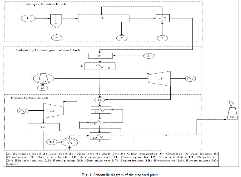 |
| The producer gas gets combusted in the presence of atmospheric air (block 8) in the combustion chamber and flue gas is generated. The flue gas then enters into the heat exchanger (block 9) as hot fluid and flows through the shell side of it. Block 8 and block 9 together called as combustor-heat exchanger duplex (CHX) unit. The atmospheric air enters into the compressor (block 10) and after getting compressed enters into the heat exchanger and gets heated. The hot and compressed air then enters into the gas turbine (block 11). The hot air after expansion mixes with the exhaust from the heat exchanger at the gas mixture (block 16). The bottoming steam cycle consisting of steam turbine (block 12), condenser (block 3) and feed pump (block 15) is used for power generation in combination with the heat recovery steam generator (HRSG) to recover exhaust heat of the topping cycle. Thus, topping GT cycle and bottoming ST cycle together operates as combined cycle. The HRSG consists of three sub-units of heat exchangers. The HRSG sub-units are superheater (SUP, block 17), evaporator (EVAP, block 18) and economizer (ECO, block 19) respectively. Minimum pinch point temperature (15 0C) is maintained in the evaporator for better heat transfer between the water and the exhaust gas mixture. The exhaust gas mixture after passing through the HRSG unit is allowed to expose in the atmosphere through stack (block 22). |
III. MATHEMATICAL FORMULATION |
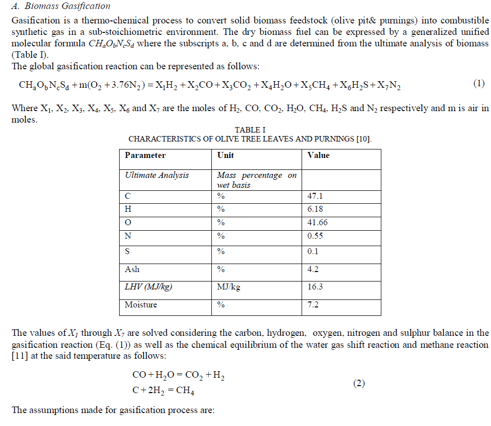 |
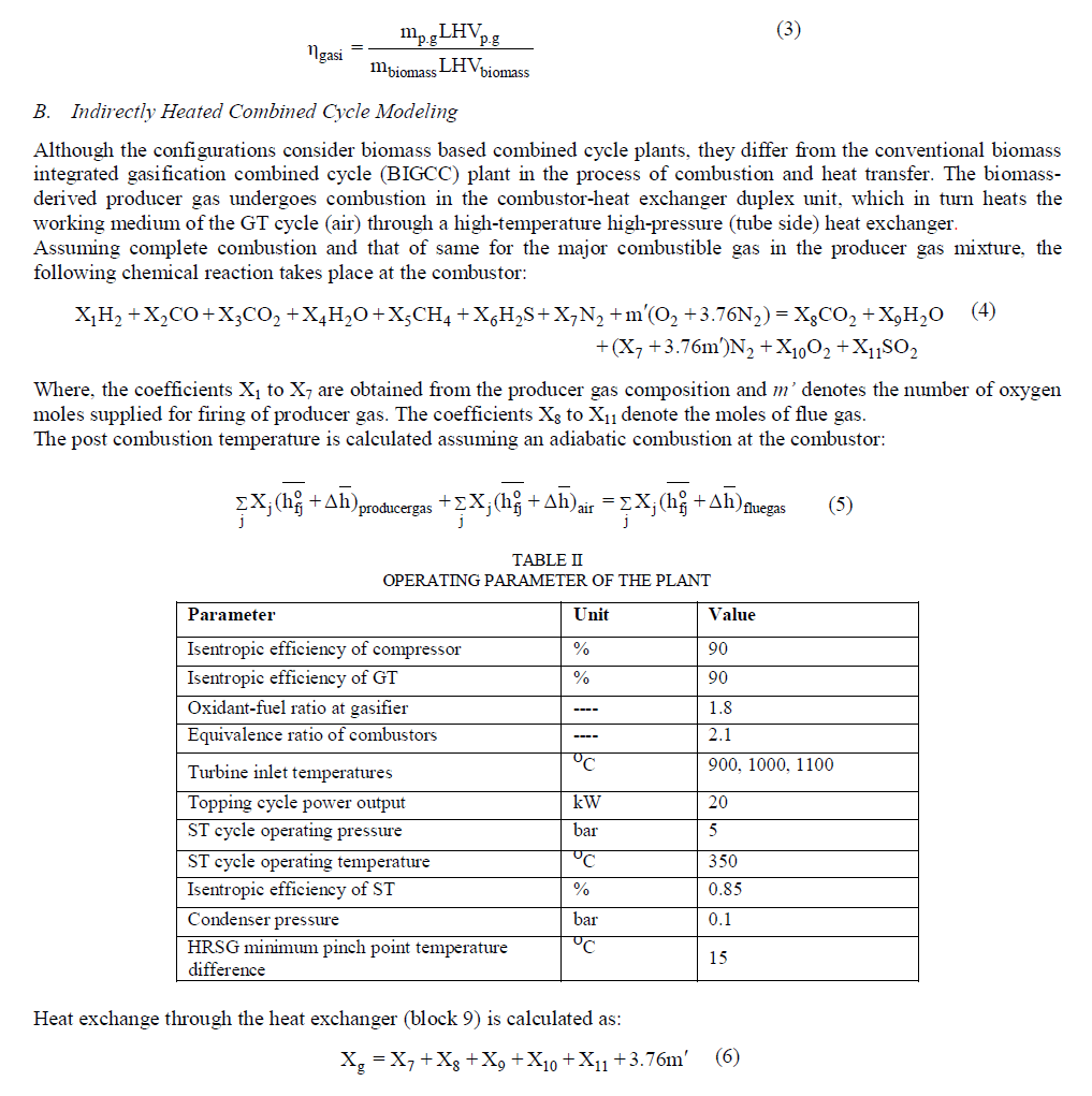
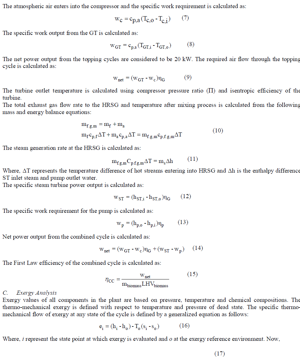
| ï· 5% (by mass) unconverted carbon (char) is assumed. ï· Ashes are mainly consisting of Al2O3, SiO2 and Fe2O3. ï· Tar formation is not considered in this model. Air blown fixed bed downdraft gasifier operating on atmospheric pressure is used in the present model. The bed temperature of the gasifier is 8000C. The gasification temperature is adjusted by controlling the oxidant (air)/biomass ratio xOF presented in Table III. To increase the gasification efficiency preheating of |
 |
 |
 |
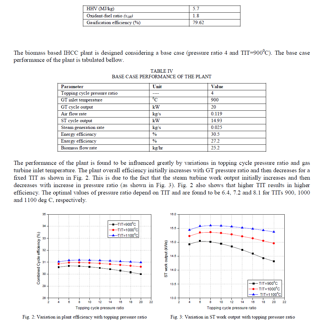 |
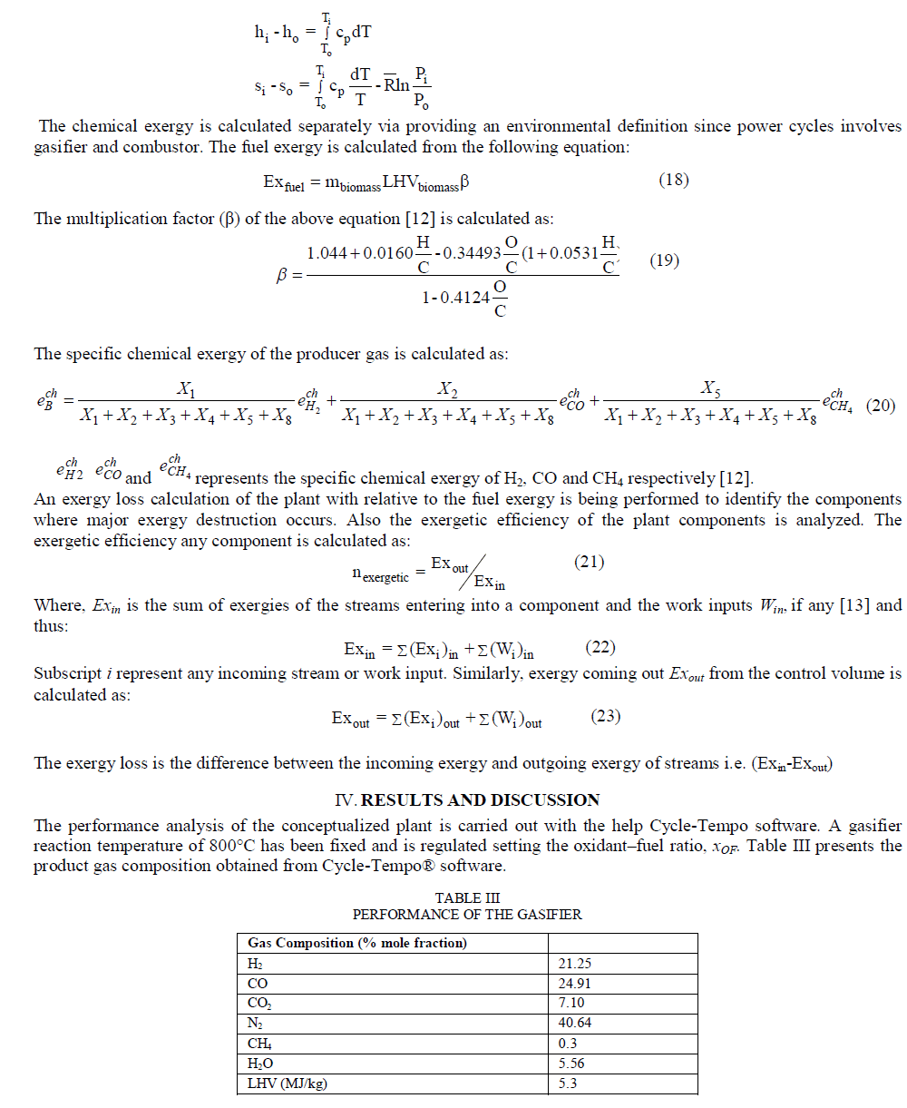
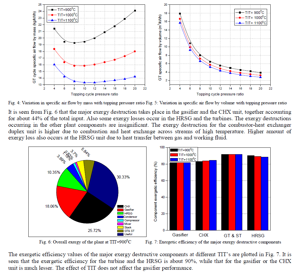
| The specific volume flow rate of air through the tubes of the CHX unit, and therefore the size of the CHX unit, is greatly influenced by the topping cycle pressure ratio. Higher topping cycle pressure ratio reduces the mass flow requirement of the GT block. This reduced mass flow rate, coupled with higher density at higher pressure, reduces the volume flow rate of air through the tubes of the CHX unit. Thus sizing of the topping cycle ducting and CHX unit decreases Figures 4 and 5 explain these variations. The exergy analysis of the plant is carried out in this paper at the optimal operating pressure ratio (ïÂÂ=8) and different TIT’s using similar methodology of Datta et al. [12]. Figure 4 shows the overall exergy of the plant with respect to fuel exergy at TIT=9000C. |
 |
V. CONCLUSION |
| A configuration is proposed for an indirectly heated combined cycle incorporating a downdraft biomass gasifier using olive leave and purnings mixture as fuel. It is observed that the plant efficiency is maximized at some values of topping cycle pressure ratio, the value which depends upon the gas turbine inlet temperature. At a particular pressure ratio, the plant thermal efficiency increases with TIT. In addition, it is found that the gas turbine pressure ratio affects the size of the plant components, as it decreases the air flow rate across the gas turbine cycle. The maximum exergy destruction occurs at the gasifier, combustor-heat exchanger duplex unit and HRSG. It is seen form the analyses that the plant can be operated at the pressure ratio value of 8 and at higher turbine inlet temperatures. |
ACKNOWLEDGMENT |
| The first author acknowledges the support provided by the Thermal Simulation and Computation (TSC) Lab at Mechanical Engineering Department of BESU, Shibpur for carrying out the research work. The authors also acknowledge the cooperation of TU Delft (Delft University of Technology), The Netherlands, for providing the Cycle- Tempo software to the (TSC) lab, which has been used for the present study. |
 |
References |
|