International Journal of Innovative Research in Science, Engineering and Technology
ISSN ONLINE(2319-8753)PRINT(2347-6710)
ISSN ONLINE(2319-8753)PRINT(2347-6710)
S.Shalman Khan 1, S.P.Stalin 2 , T.Hari Vijaya Kumar 3
|
| Related article at Pubmed, Scholar Google |
Visit for more related articles at International Journal of Innovative Research in Science, Engineering and Technology
This paper concentrates on the study of effective implementation of the magnetic repulsion principle. A magnet is a material or object that produces a magnetic field that is invisible but is responsible for the most notable property of a magnet: a force that pulls on other ferromagnetic materials, such as iron, and attracts or repels other magnets. Though the occurrence of magnets in nature is of various forms and structures we chose ferrite magnets. The reason would be very simple that ferrite is the only magnet with relatively low cost by weight. By the same time, it can also afford a good magnetic field with a maximum value of 0.2 tesla. The model has been constructed and the experiment has been conducted with the help of ferrite magnets mounted on Aluminium arms. The results show that the acceleration is being produced in the vehicle. A significant reduction in the rider’s effort was noticed after the incorporation of the model lodging clustered magnets.
Keywords |
| Tesla, ferrite, repulsion, acceleration, magnets, ferromagnetic |
INTRODUCTION |
| There is an escalating stipulate for advanced materials with better properties to meet new requirements or to replace existing materials. In this regard we consider ferrite as the most suitable material. A permanent magnet is an object made from a material that is magnetized and creates its own persistent magnetic field. And it is well known that a permanent magnet will never undergo demagnetization. In this study an attempt has been made to study the effect of principle of magnetic repulsion in the rider’s effort who is riding a cycle. It is a fact that the model is compatible with any kind of cycle and it adheres to any situation. As we have seen, the recent developments in the mechanical discipline with the aid of electric and electronic components the magnet is thought to be least important. The paper revolves around a simple principle of magnetic repulsion. The reason for choosing a permanent magnet is its persistent magnetic field. The model of the concept can be incorporated in a cycle easily. The clear view of the setup has been provided in the paper and interpreted. Initial research uncovered the idea that the orientation of magnetic field from other faces disturbs the required repulsion in the north-pole faces. This shortcoming could have been overcome by the usage of some isolating materials like Mu-metal or stainless steel. But this is also less possible since the Mu-metal absorbs the entire magnetic field also from the north-pole. Thus the required repulsive force was less in magnitude. We were greatly inspired to create a project to determine if the magnetic repulsion really helps to reduce the effort of a rider. Based on previously stated research, our hypothesis was that it is sure that the effort is greatly pacified. We had tried our level best to fulfil the satisfaction of the beneficiary through our project. |
II. MAGNETISM AND MATERIAL SELECTION |
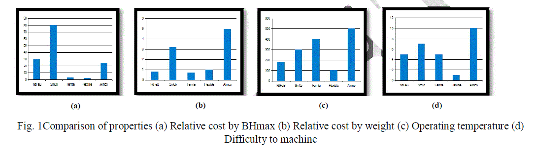
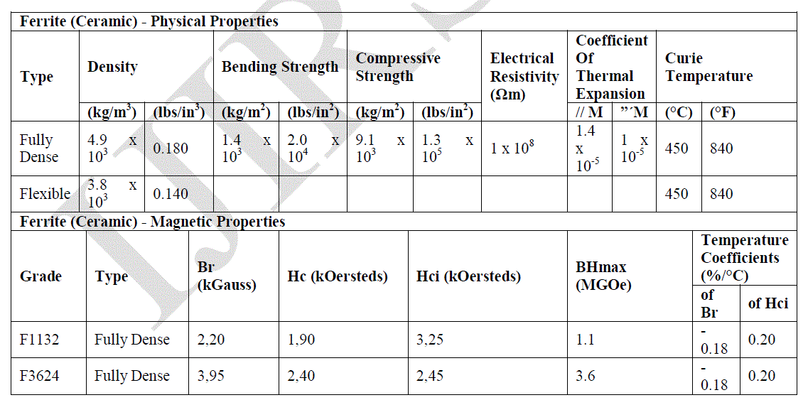
| Ferromagnetic and ferrimagnetic materials are the ones normally thought of as magnetic; they are attracted to a magnet strongly enough that the attraction can be felt. These materials are the only ones that can retain magnetization and become magnets; a common example is a traditional refrigerator magnet. Ferrimagnetic materials, which include ferrites and the oldest magnetic materials magnetite and lodestone, are similar to but weaker than ferromagnetic. The difference between ferromagnetic and ferrimagnetic materials is related to their microscopic structure, as explained in Magnetism.Magnetic fields are produced by moving electric charges and the intrinsic magnetic moments of elementary particles associated with a fundamental quantum property, their spin. It is denoted by B. Its unit is Tesla. The magneticmoment of a magnet is a quantity that determines the torque experienced in an external magnetic field. It is denoted by m. The magnetization of a magnetized material is the local value of its magnetic moment per unit volume, usually denoted M. The most commonly used magnetic materials are Neodymium Iron boron, Samarium cobalt, Alnico, Ferrite (ceramic), Ferrite (Flexible). Their properties have been compared in Fig 1. |
 |
 |
 |
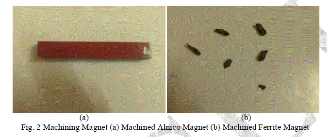 |
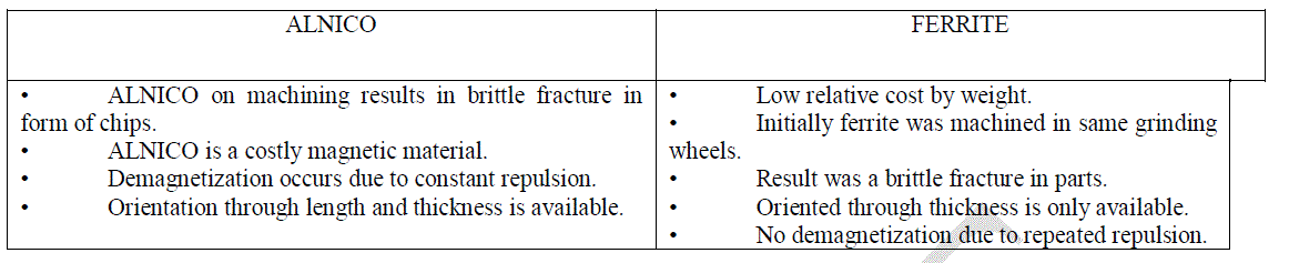
| The machining of Alnico magnet resulted in small chip formation without any large brittle failure as shown in Fig 2(a). The machining of Ferrite magnet resulted in large brittle fracture leading to formation of fragments as shown in Fig 2(b). |
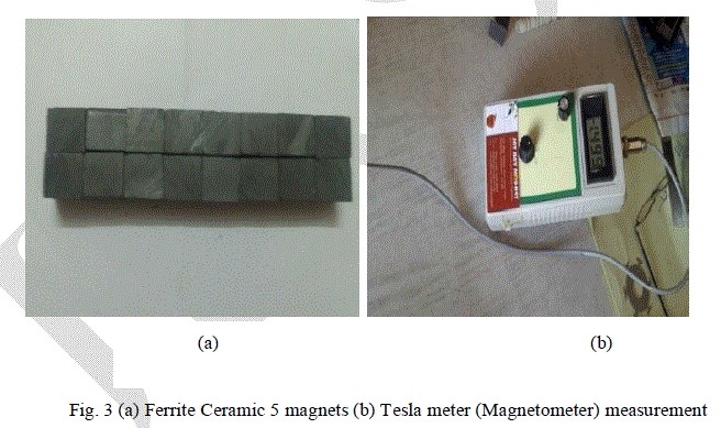 |
| The Fig 3(a) shows the permanent ferrite magnets used for the experiment and Fig 3(b) shows the tesla reading for those magnets. The secondary components used for holding magnets are manufactured using aluminium. Aluminium is a soft, durable, lightweight, ductile and malleable metal with appearance ranging from silvery to dull grey, depending on the surface roughness. It is nonmagnetic and does not easily ignite. A fresh film of aluminium serves as a good reflector (approximately 92%) of visible and an excellent reflector (as much as 98%) of medium and far infrared radiation. The yield strength of pure aluminium is 7–11 MPa, while aluminium alloys have yield strengths ranging from 200 MPa to 600 MPa. Aluminium has about one-third the density and stiffness of steel. It is easily machined, cast, drawn and extruded. |
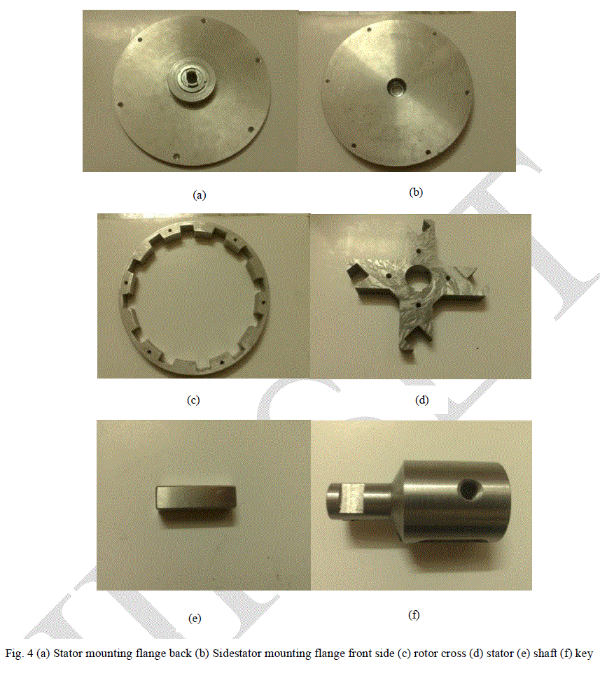 |
| The components mentioned in Fig 4 has been fabricated by means of Computer Numerical Coding using accurate coordinates to maintain right clearance in concentricity. |
III. DESIGN AND WORKING PRINCIPLE |
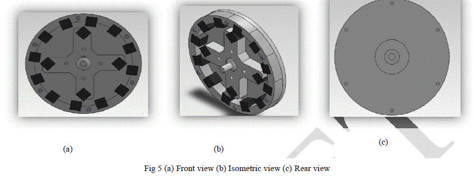 |
| The Fig 5 shows the Front (a), Isometric (b) and Rear (c) views of the working design. It comprises of model designed by means Solidworks modelling software implementing respective material properties. |
| The proposed design can be fitted to the pedal shaft of any cycle. The design of the stator and rotor along with magnets are in such a way that they have a clearance of about 1mm which avoids the collision between their edges at higher speeds of rotation. The stator is bolted to a stator mounting flange which in turn is mounted on the pedal shaft of the cycle. The rotor is placed inside the stator that their axes are coinciding each other. Rotor shaft is keyed to the rotor and this helps to rotate the rotor on applying torque to the pedal. The pedal shaft is inserted into the hollow portion of the rotor shaft and tightened by means of crush screws. The magnets are placed and pasted in the respective slots provided using araldite. Now the whole assembly is ready to be incorporated in any cycle. |
| The working principle of the magnetic repulsion mechanism has been clearly explained below: |
| The working principle involves common magnetic properties of like poles repel and unlike poles attract each other. Since Curie temperature is not reached as a result of this mechanism, hysteresis curve is not affected. The magnetic field acting in this mechanism is just between the magnets and there is no field action with any of the secondary components. The reason is that the secondary components are manufactured by using aluminium 1100 (non-magnetic material). After the provision of initial torque, the stator magnets constantly accelerates the rotor by means of angular deflective force caused due to north-north repulsion at a particular rated speed. |
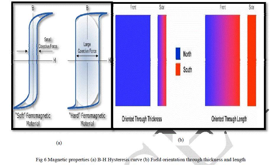 |
| The function of the permanent magnet is mainly dependent on the repulsive force. The polarity is another factor which influences this mechanism to the most. The orientation of the polarity along the thickness and along the length must be supportive in this mechanism. Since the magnet chosen for this mechanism possess cubic structure, it is independent of the orientation factor. The effect of field variation along the distance has effectively discussed below. |
IV. INVESTIGATION OF MAGNETIC FIELD |
| The magnetic field B (Gauss) varies with respect to distance. This is clearly shown in the table (3) given below. |
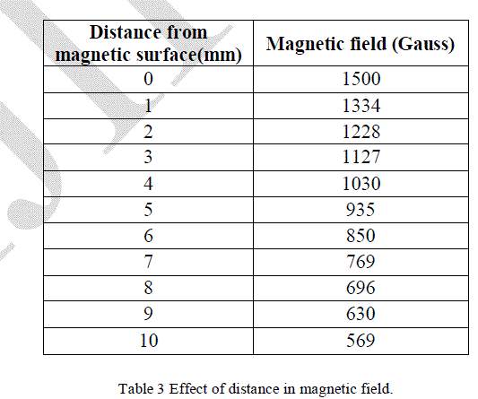 |
| Table (3) comparison between distance from magnetic surface and magnetic field in gauss. |
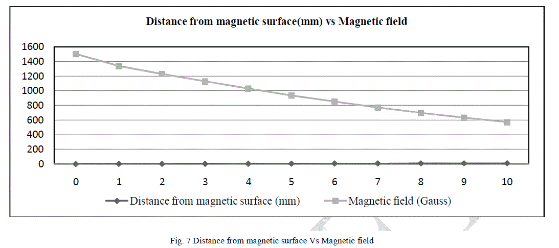 |
| The graph clearly states that the effect of magnetic field decreases exponentially with respect to the distance. |
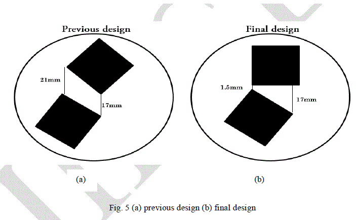 |
| The initial design in Fig 5(a) had two extreme edges of magnet at large distances 21mm and 17mm respectively. The Final design is a well optimized with one extreme well nearer with 1.5mm gap and other with 17mm gap. |
 |
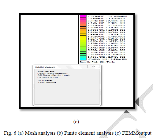 |
| The figure 6 clearly states the analysis done in Finite Element Method Magnetics software. |
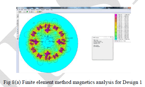
FIELD DISTRIBUTION FINITE ELEMENT METHOD MAGNETICS ANALYSIS FOR DESIGN 1: |
| The following analysis is made for assembly design with magnets placed at the rotor and the stator. The ceramic 5 magnet was chosen from material library as the magnet material. This is a 2D PLANAR ANALYSIS made by creating mesh with 40832 nodes and 81437 elements. The density plot of the magnetic field (TESLA) has been shown. |
 |
| FINITE ELEMENT METHOD MAGNETICS ANALYSIS FOR DESIGN 2 |
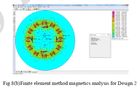 |
| The design 2[Fig 8(b)] which has been analysed through FEMM reveals a fact that reduces the distraction due to polarity along the thickness on a comparative basis to design 1[Fig 8(a)]. |
V. DESIGN CALCULATION |
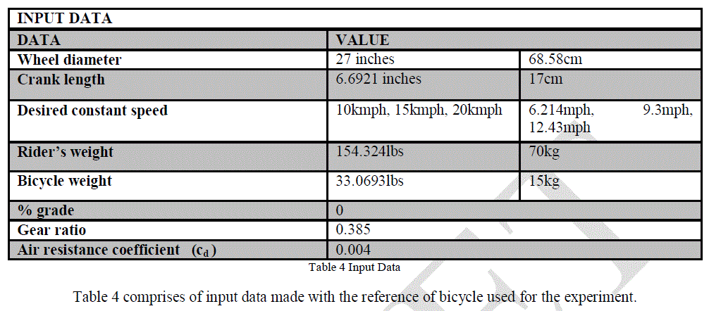 |
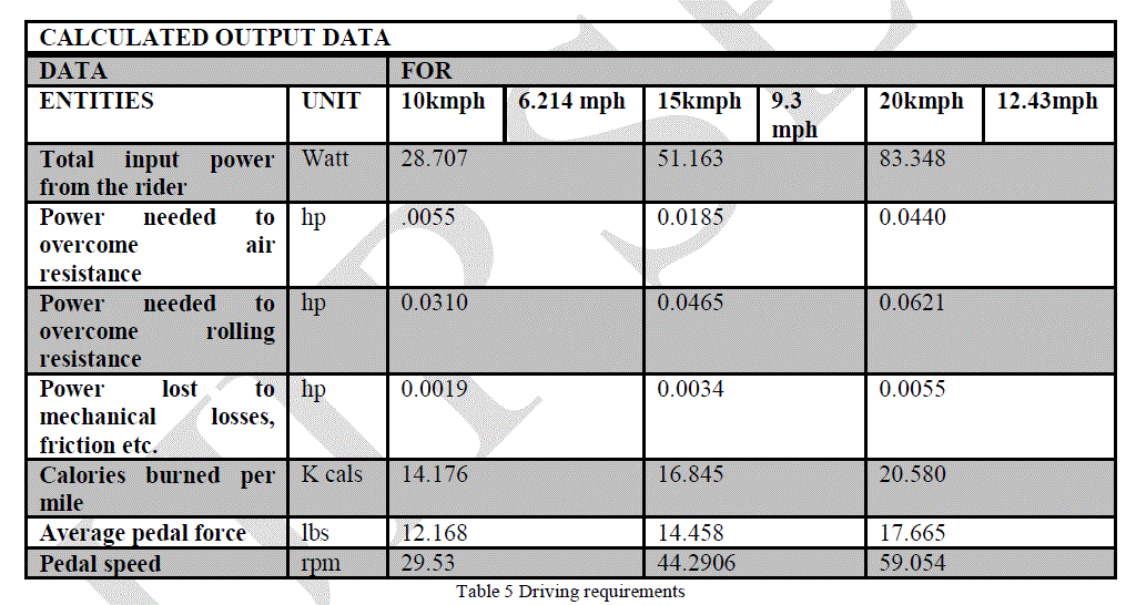
| Table 6 comprises of results obtained as output and magnetic requirements to drive the bicycle specified in input data table (Table 4) |
VI. EXPERIMENTAL RESULTS |
| The experimental result for the fabricated design is tested by means of a bicycle. A 70kg rider is made to ride a distance 15km (9.3 miles) per hour with cycle with and without this fabricated magnetic attachment. At the end his heart rate per minute was measured and the calorie burned was calculated. |
 |
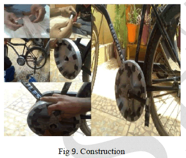 |
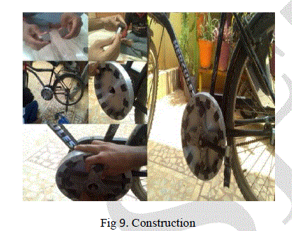
| The Fig 9 shows the construction of the magnetic repulsion mechanism. |
VII. CONCLUSION |
| The journal explained comprises of concepts about an optimized cycle where people favour both exercising factor and less calorie burning factor in case of riding a cycle. The above fabricated product is user friendly that it fits in any bicycle.Finally we would like to conclude that the proposed design could be still improved based on the application of alternate shapes of magnets with finite element method magnetics software. An interesting future study might involve testing the magnets at different patterns to simulate a further worthy mechanism. |
References |
|