ISSN ONLINE(2319-8753)PRINT(2347-6710)
ISSN ONLINE(2319-8753)PRINT(2347-6710)
Suhas B1 and A R Anwar Khan2
|
| Related article at Pubmed, Scholar Google |
Visit for more related articles at International Journal of Innovative Research in Science, Engineering and Technology
A steam turbine rotating system is loaded with time by the changes in stress levels as a result of start-up and shutdown procedures.Many of the most serious damage mechanisms in blades occur in the phase transition zone (PTZ) This region typically starts in low pressure (LP) turbines and fails typically because of low cycle fatigue and creep. The purpose of this paper is to investigate the low cycle fatigue failure of low pressure steam turbine blade, particularly near PTZ. The present work is primarily focused developing a technique to assess low cycle fatigue life of the blade and to determine the number of startups and shutdown cycles. Two approaches were employed. First approach is based on the elastic finite element (FE) analysis. Second approach is based on elastic-plastic FE analysis. Strain amplitude is determined directly from the FE analysis and fatigue life is assessed Morrow’s equation. Creep life due to strainhardening is also assessed by using creep laws.
Keywords |
| Low pressure steam turbine blade, linear stress analysis, bilinear stress analysis, low cycle fatigue, creep, ANSYS. |
INTRODUCTION |
| A steam turbine is a device that extracts thermal energy from pressurized steam and uses it to do mechanical work on a rotating output shaft. It has a rotating wheel to which is secured a series of buckets, blades or vanes, uniformly spaced on its periphery.The thermodynamic cycle for the steam turbine is the Rankine cycle, It basically consists of a rotor from which project several rows of closely spaced blades. Between each row of moving blades there is a row of fixed blades that project inward from a circumferential housing. |
| Walter Hossli, [1] in his paper he has discussed that, Structural integrity of all rotating components is the key for successful operation of any turbomachinery.The challenge with rotating equipment, such as turbomachinery, is often more severe due to the significance of the alternating loads that must be carried to satisfy their purpose.One of the causes of blade deterioration is static stress which is primarily the result of steam bending and centrifugal loads. |
| Metal fatigue is a process which causes premature failure or damage of a component subjected to repeated loading.One of the most important physical observations is that the fatigue process can generally be broken into two distinct phasesinitiation life and propagation life. The initiation life encompasses the development and early growth of a small crack. The propagation life is the portion of the total life spent growing a crack to failure.Strain life approach method usually considered an initiation approach. It is used when the strain is no longer totally elastic, but has a plastic component. Short (low cycle) fatigue lives generally occur under these conditions. |
LITERATURE SURVEY |
| The stresses in blade are a combination of direct tensile load due to centrifugal force and the bending load due to steam force was explained by Arkan K. Husain Al-Taie [2]. Most highly stressed parts of steam turbines in electrical power generation systems are bladed disks especially low-pressure blades that undergo the greatest centrifugal force and bending produced in the entire turbine. |
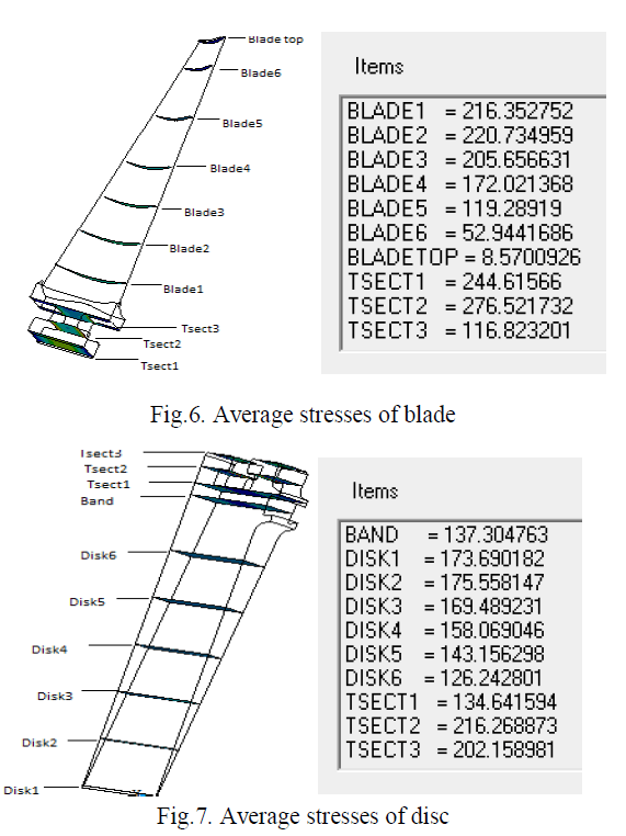
| The concept of determining average stress in mating surfaces was first introduced by Kumar K et al. [3]. The stress in the mating surfaces are fully elastic and generally well below yield, peak stress at some contact regions in the slot can reach yield values and extend into the local plastic region of the material. Cracks start at these high-stress locations and propagate causing fatigue failure and turbine shutdown. |
| K.Gopinath, [4] in his work he has discussed that fatigue occurs when a material is subjected to repeated loading and unloading and when rotating machine components are subjected to external loadings, the induced stresses are not constant even if the magnitude of the applied load remains invariant. |
| Strain-life design method was introduced by Coffin-Manson and fatigue damage is assessed directly in terms of local strain. It is used for the prediction of the crack initiation period. |
| M. A. Meyers, [5] in his work he has discussed that creep is temperature dependent and always increases with temperature. Meyer suggested that creep also depends on the magnitude of the applied stress and its duration; the deformation may become so large that a component can no longer perform its function. |
| Dr. Ahmed N.Al-khazraji, [6] in his paper he has discussed that Residual stresses canoccur under any circumstances that lead to differential expansion or contraction between adjacent parts of a body in which the local yield strength is exceeded. Tensile residual stresses in the surface of a component are generally undesirable as they contribute to the major cause of fatigue failure, quench cracking and stress corrosion cracking.Compressive residual stresses are usually beneficial since they increase fatigue strength, resistance to stress-corrosion cracking, and increase the bending strength. |
| Paper is organized as follows. Section III describes briefly problem definition. After defining the problem, the method of solving the problem is given in Section IV. Section V presents the simulation oflinearstatic analysis, bilinear structural analysis, Low cycle fatigue analysis and creep analysis which is carried out using ANSYS commercial software and the results are listed. Finally,Section VI presents conclusion. |
PROBLEM DEFINITION |
| Most of the steam turbine blades work on very high temperature and loads. In this present work we calculate the maximum stress and maximum deformation on the T-root of the low pressure large steam turbine blade. Linear and bilinear stress analysis has to be performed using ANSYS-14.5 commercial software. Life of the bladed disc is to be estimated using Morrow’s equation and results are compared with ANSYS fatigue tool.Creep analysis is carried out using creep law to estimate the life of the blade in creep hours. |
METHODOLOGY |
| PRELIMINARY DESIGN CONSIDERATIONS |
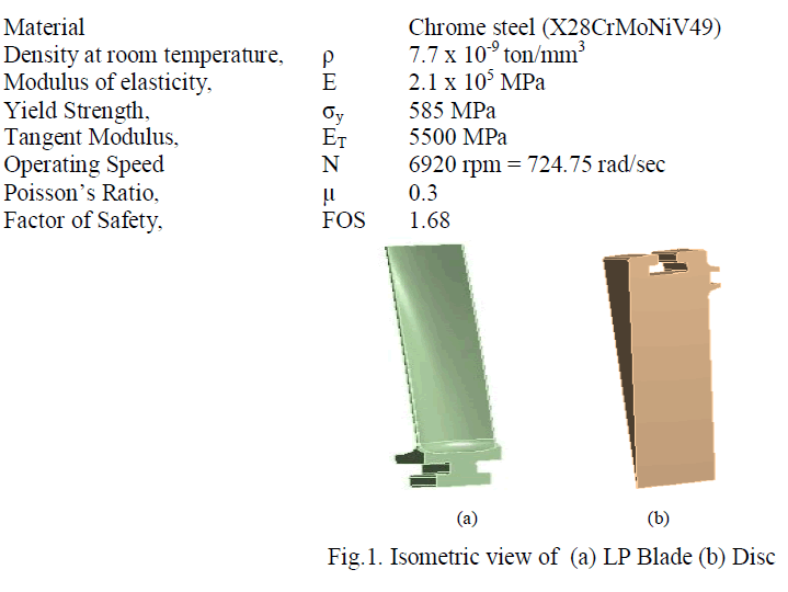 |
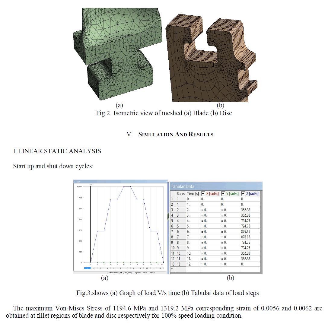
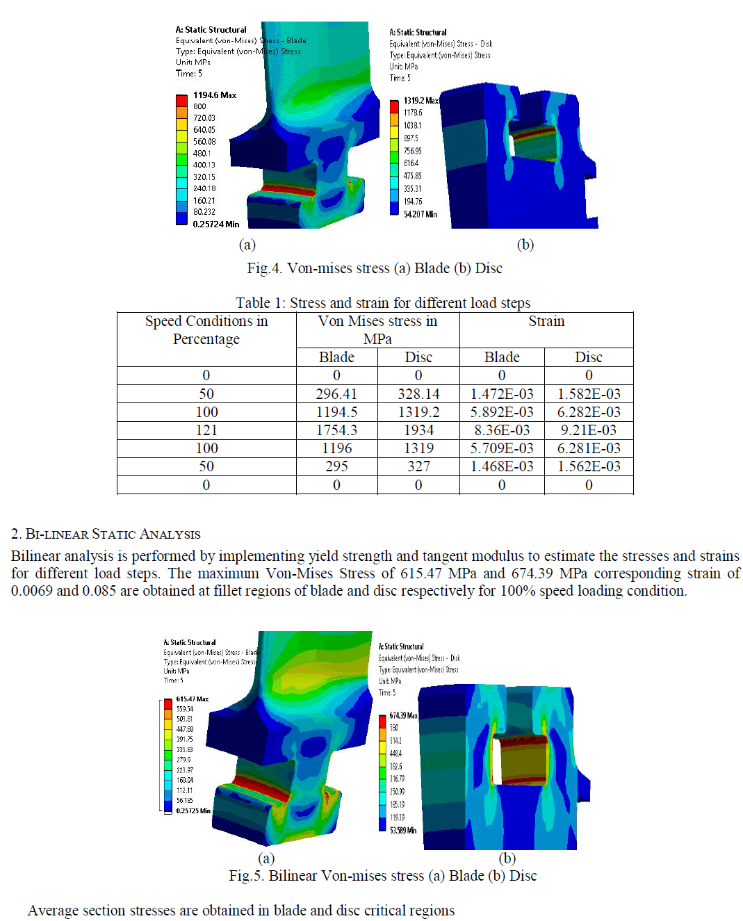
| The model of the low pressure T-root steam turbine blade and disc is created using Pro-E and the geometry is imported to FE tool. The FE model is created using 3D tetra elements with 27336 elements and 73664 nodes. Contact regions are specified in the T root of blade and disc with co- efficient of friction of 0.2. Rotational velocity is applied in load steps. The bladed disc is constrained along Y and Z directions. Cyclic symmetry model is created in order to simulate all the bladed disc assembly. |
 |
 |
 |
3. LOW CYCLE FATIGUE ANALYSIS |
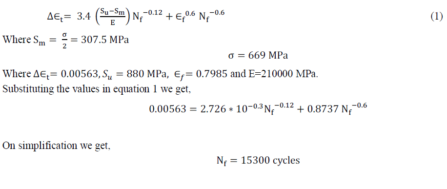
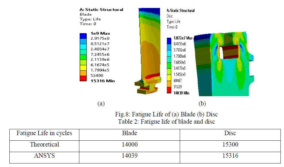
| Fatigue life of blade and disc are estimated using strain life approach and results are compared with fatigue tool. The fatigue life of the geometry model is found to be 15300 cycles. This is said to be a safe value for a turbine blade, used in industries over a period of 20 years. |
| By morrow’s relation, |
 |
 |
4. CREEP ANALYSIS |
| Creep life in hours of blade and disc are obtained using creep strain. The creep strain is calculated from bilinear analysis results. |
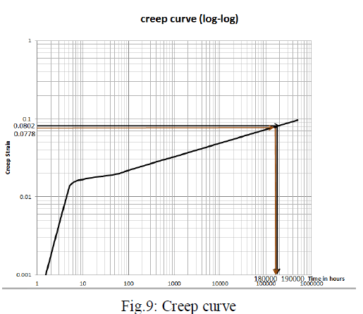 |
| From the above curve we have found that the creep life of the blade is 180000 hours and that of Disc is 190000 hours. |
CONCLUSION |
| From the above results we have found that since the peak stress in bilinear analysis at the T-root is more than the yield strength, the average stress in the T-root is less than the yield stress, as a result the Bladed Disc model is safe for an efficient performance in Industries. |
| The fatigue life of Blade and Disc are more than 10000 cycles as found by the theoretical and analytical analysis, hence the blade and disc can be made usein thermal power plants for more than 20 years without fatigue failure leading to turbine shutdown. |
| The creep life of the Blade and Disc are found to be more than 172800 hours, as a result the Bladed and Disc can perform efficiently for more than 20 years without leading to creep failure. |
References |
|