ISSN ONLINE(2319-8753)PRINT(2347-6710)
ISSN ONLINE(2319-8753)PRINT(2347-6710)
Prof. Dr. Abdul-Hassan K. Al-Shukur , Dr.Safaa K. Hashim Al-Khalaf , Ishraq M. Ahmed Al-sharifi
|
| Related article at Pubmed, Scholar Google |
Visit for more related articles at International Journal of Innovative Research in Science, Engineering and Technology
This study based on laboratory experiments aims to investigate the flow characteristics and energy dissipation rates on six different configurations of steps of stepped spillway which are: (Inclined and endsills which were fixed on the downstream of the horizontal face of all steps, alternative endsills and horizontal steps, steps combined with endsills and inclined started with endsills and steps combined with endsills and inclined but started with inclined), at physical model with ratio height to length of step (h/l= 0.8391) and (h=3cm) at skimming flow regime. Flow discharge variations were applied in each configuration and the hydraulic changes were investigated and energy dissipation rates were calculated and compared with conventional type of step of stepped spillway. The results showed that the using of different types of steps have the most influence on the amount of energy losses, they are increased the energy losses by about (1.6%-18.6%) at different runs and configurations in comparison of horizontal steps. The results indicated also that the energy dissipation rate at configuration of alternative inclined and horizontal steps show increased by about (6.2% at q=0.02119 m3/s/m) more than the configuration of alternative endsills and horizontal steps and by about (5.3% at q=0.02119 m3/s/m) more than configurations of inclined on all steps. Furthermore, use of compound horizontal and inclined steps alternatively has better performance in dissipating the flow energy in comparison with the horizontal steps, it is increased in the energy dissipation rate up to about (18.6 %) at (q=0.02119 m3/s/m).
Keywords |
| Endsills,Energy dissipation, inclined, stepped spillway,skimming flow regime. |
INTRODUCTION |
| Stepped spillways are hydraulic structures that have regained significant interest for researchers and dam engineers in the last two decades, specially due to technological advances in construction of Roller Compacted Concrete (RCC) dams [4]. The stepped channel and spillways have been used for centuries, since more than (3000) years [9] where were selected to contribute the stability of the dam and for their simplicity in shape [6]. The advantage of stepped spillway include ease of construction, reduction of cavitation risk potential, as well as reduction the stilling basin dimensions at the downstream dam toe due to significant energy dissipation along chute [3]. Another common application is the using of stepped overlays on the downstream face of hydraulically unsafe embankment dams as emergency spillways to safely pass a flood such as the PMF over the crest over the dam[12] . Stepped spillways are also utilized in water treatment plans. The waterfalls were landscaped as leisure parks and combined flow aeration and aesthetics [5]. The step geometry of stepped spillway can be horizontal, inclined (upward or down ward) and pooled step. For a given chute geometry, the flow pattern may be either nappe flow at low flow rates, transition flow for intermediate discharges or skimming flow at larger flow rates [7]. |
II. ENHANCEMENT OF ENERGY DISSIPATION |
| By progressing technology and innovating the technique known as R.C.C., construction of stepped spillways has been made much faster and simpler and this has been caused the designers tend to use this kind of spillways more and more as one of the best energy dissipaters. This fact should consider that the more flow energy is well-dissipated on the spillway, the more the dimensions of the stilling basin reduce and the construction cost will be more economical. By the increase of the use of stepped spillways continually, the researchers have been concentrating on the increasing efficiency of this kind of spillways and due to this fact, several methods have been presented. In this regard, the finding of the optimal dimensions of the steps according to the passing flow regime can be mentioned. In order to amplify the dissipation of energy on stepped spillways, reverse slope with different angles accompanied with different endsills installed on the edge of the steps [11]. Recently, an endsills and inclined steps for maximum energy dissipation was suggested and was found to achieve greater energy dissipation was achieved with inclined-upward steps. Enhancement of energy dissipation may be provided by the superposition of small and large steps. In Australia, the Malmsbury (1870) and Upper Coliban (1903) dam spillways were designed with a combination of large drops (h = 2 to 4 m) and stepped chutes (h = 0.305 m). At design flows, the drops operate with nappe flow and the chutes in skimming flow regime. Their successful operation for more than a century suggests that the design is sound. On the model of the Kennedy’s Vale dam (h/l = 1), Stephenson (1985) superimposed occasional large steps to smaller steps and he observed a (10%) increase in energy dissipation for the model. James et al. (2001) observed larger rates of energy dissipation with V-shaped step edges [10]. A solution to obtain an optimal efficiency to dissipate energy dissipation would be to design the steps with various types of chutes: horizontal steps, inclined steps and steps with endsills. This study presented the experimental results and characteristics of energy dissipation on different types of stepped chutes at skimming flow regime, considering this fact, most likely condition encountered in prototypes is design on this regime [8]. In order to achieve this regime the investigation was at non-dimensional ratio of height to length of the step (h/l =0.8391) for (h=3cm). |
III. EXPERIMENTAL SETUP |
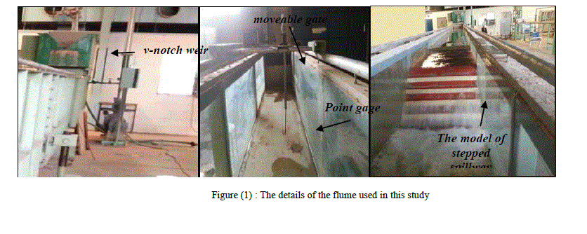
| All experiments were conducted in a prismatic rectangular flume of width 0.5m, depth 0.5m and length 18.6m. The centrifugal pump lies beside the flume at upstream, and it is having a rate capacity of (40 l/s) was used to deliver flow to the flume. For flow discharge measurement a 90 V-notch sharp crested weir located at the upstream to measuring the actual discharge pass through the flume section. At the end of the flume, moveable gate is installed to regulate the tail water depth of hydraulic jump. A water gage with 0.05 accuracy was used to measure the depth of flow after jump was fixed at a distance long enough to be in the non-aerated tail water of the jump (Y2), at (125cm) downstream the toe of the models. Figure (1) show the details of the flume used in this study. |
 |
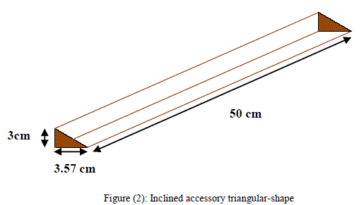
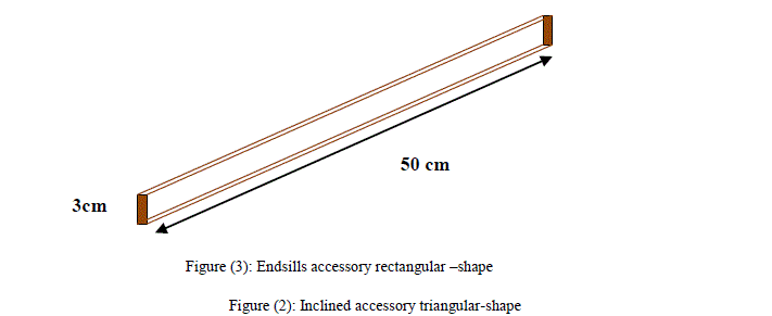
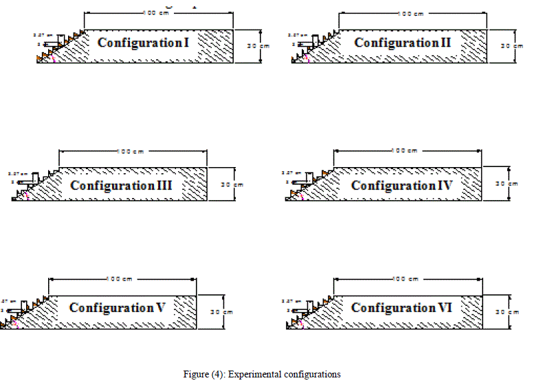
| Six configurations on different types of steps were using in the experimental laboratory as shown in figure (4),which are: (inclined and endsills which were fixed on the downstream of the horizontal face of all steps, alternative inclined and horizontal steps, alternative endsills and horizontal steps, steps combined with ends sill and inclined started with endsills and steps combined with endsills and inclined but started with inclined), at physical model with ratio height to length of step (h/l= 0.8391) and (h=3cm) at skimming flow regime. Ten pieces of wood were modeled on six configurations were studied in the laboratory as shown in figures (2)&(3). All configurations have the same spillway slope, spillway height, number of steps and length,(i.e. 400, 30cm, 10 and 135.75cm respectively). These pieces were made of wood with a smooth surface and they were painted with varnish to avoid swelling and to reduce the roughness coefficient of the models in agreement with concrete roughness coefficient. |
| i. Inclined group: It consists of inclined pieces which have a triangular-shape with (50cm) length and thickness (3cm) as shown in figure (2), to produce adverse bottom slope (θ=400), it was fixed on the downstream of the horizontal face of all steps (configuration I) and of alternative steps (configuration IV), see figure (4). |
 |
| ii. Endsills group: It consists of rectangular shape of endsills with length, width and thickness (50cm, 1cm and 3cm) respectively as shown in figure (3). It is attached the downstream of horizontal face of all steps (configuration II) and on alternative steps (configuration III) as shown in figure (4). |
 |
| iii. Combined group: It consists of alternative endsills and inclined started with inclined (configuration V), and alternative endsills and inclined but started with endsills (configuration VI) as shown in Figure (4). All the endsills and inclined have the same dimensions as first and second groups above. |
 |
IV. THE EFFECT OF USING DIFFERENT CONFIGURATIONS ON FLOW BEHAVIOR |
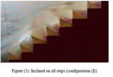
| In condition of skimming flow regime, at the configuration of inclined and endsills, the water flows over the brink of the steps act as flow over very rough chute. The characteristic height increases the volume of trapped water. In comparison between flow on inclined steps and horizontal steps shows that the inclined steps is effecting on lower limit on skimming flow regime, it is increased slightly with inclined steps at some lower discharge and there is no effect observed at higher discharge. Figure (5) show the flow at inclined steps (configuration (I)) . |
 |
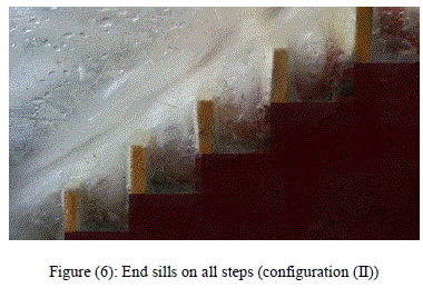
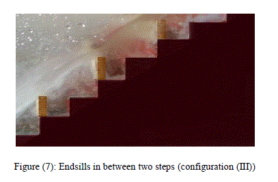
| In configuration (II) which endsills on all the steps, at the skimming layer, the zones under the influences of the internal jet becomes thinner at the endsills outer edge compared to the case of steps corner, the endsills do not contribute to a major modification of the flow regime, however, the sizes are slightly modified, this has a direct effect on a contact length between recirculating cells and steps face as well as on the impact zone of internal jet. The vertical length of the vortex increase while the horizontal length is extended to the toe of the endsills as shown in figure (6), for the steps without endsills (configuration (III)), the vortex impact the entire vertical and horizontal step face (see figure 7). |
 |
| The alternative endsills and horizontal steps significantly influence the onset of the skimming flow. In fact, the flow is subject to a larger acceleration prior to hitting the next endsills, where it is deflected, as a result, the air pocket in the subsequent downstream step (without endsills) remains in the cavity for higher discharge as shown in figure (7) below. |
 |
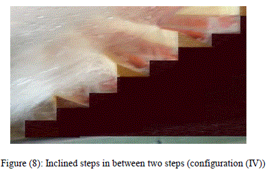
| Alternative inclined and horizontal steps (configuration (IV)) presents quite the same criteria for the alternative endsills and horizontal steps (configuration (III)). However, the onset of skimming flow is attained sooner as compared with horizontal steps. It is judged that air cavities are rapidly filled with water because the flow is free to circulating between two steps. Figure (8). |
 |
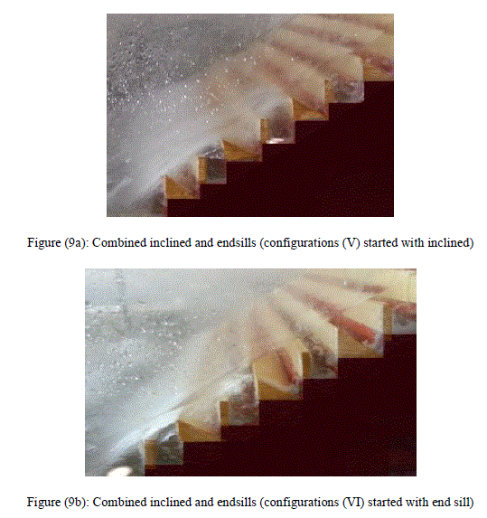
| With combined the inclined with the endsills at configurations (V&VI), it can be observed the same characteristics of configurations (I&II) for higher discharge. With reduction the discharge, air pocket can be seen when the flow is passing from the inclined steps to steps with endsills. This result to shout the flow because there is no enough space to fill the water in this air pocket as shown in Figure (9a) & (9b). The alternative inclined and endsills in first step doesn’t have remarkable effect on the flow behavior. |
 |
V. INFLUENCE OF DIFFERENT CONFIGURATIONS ON ENERGY DISSIPATION RATES |
1. Sources of Energy Dissipation |
| ISSN: 2319-8753 International Journal of Innovative Research in Science,Engineering and Technology (An ISO 3297: 2007 Certified Organization) Vol. 3, Issue 1, January 2014 Flow Characteristics and Energy Dissipation Losses in Different Configurations of Steps ofStepped Spillway Prof. Dr. Abdul-Hassan K. Al-Shukur , Dr.Safaa K. Hashim Al-Khalaf , Ishraq M. Ahmed Al-sharifi Department of Civil Engineering, University of Babylon / Babil Department of Civil Engineering, University of Kufa/Najaf , Student, Department of Civil Engineering, University of Kufa/Najaf Abstract:This study based on laboratory experiments aims to investigate the flow characteristics and energy dissipation rates on six different configurations of steps of stepped spillway which are: (Inclined and endsills which were fixed on the downstream of the horizontal face of all steps, alternative endsills and horizontal steps, steps combined with endsills and inclined started with endsills and steps combined with endsills and inclined but started with inclined), at physical model with ratio height to length of step (h/l= 0.8391) and (h=3cm) at skimming flow regime. Flow discharge variations were applied in each configuration and the hydraulic changes were investigated and energy dissipation rates were calculated and compared with conventional type of step of stepped spillway. The results showed that the using of different types of steps have the most influence on the amount of energy losses, they are increased the energy losses by about (1.6%- 18.6%) at different runs and configurations in comparison of horizontal steps. The results indicated also that the energy dissipation rate at configuration of alternative inclined and horizontal steps show increased by about (6.2% at q=0.02119 m3/s/m) more than the configuration of alternative endsills and horizontal steps and by about (5.3% at q=0.02119 m3/s/m) more than configurations of inclined on all steps. Furthermore, use of compound horizontal and inclined steps alternatively has better performance in dissipating the flow energy in comparison with the horizontal steps, it is increased in the energy dissipation rate up to about (18.6 %) at (q=0.02119 m3/s/m). Keywords:Endsills,Energy dissipation, inclined, stepped spillway,skimming flow regime. I. INTRODUCTION Stepped spillways are hydraulic structures that have regained significant interest for researchers and dam engineers in the last two decades, specially due to technological advances in construction of Roller Compacted Concrete (RCC) dams [4]. The stepped channel and spillways have been used for centuries, since more than (3000) years [9] where were selected to contribute the stability of the dam and for their simplicity in shape [6]. The advantage of stepped spillway include ease of construction, reduction of cavitation risk potential, as well as reduction the stilling basin dimensions at the downstream dam toe due to significant energy dissipation along chute [3]. Another common application is the using of stepped overlays on the downstream face of hydraulically unsafe embankment dams as emergency spillways to safely pass a flood such as the PMF over the crest over the dam[12] . Stepped spillways are also utilized in water treatment plans. The waterfalls were landscaped as leisure parks and combined flow aeration and aesthetics [5]. The step geometry of stepped spillway can be horizontal, inclined (upward or down ward) and pooled step. For a given chute geometry, the flow pattern may be either nappe flow at low flow rates, transition flow for intermediate discharges or skimming flow at larger flow rates [7]. Copyright to IJIRSET www.ijirset.com ISSN: 2319-8753 International Journal of Innovative Research in Science, Engineering and Technology (An ISO 3297: 2007 Certified Organization) Vol. 3, Issue 1, January 2014 Copyright to IJIRSET www.ijirset.com 8824 II. ENHANCEMENT OF ENERGY DISSIPATION By progressing technology and innovating the technique known as R.C.C., construction of stepped spillways has been made much faster and simpler and this has been caused the designers tend to use this kind of spillways more and more as one of the best energy dissipaters. This fact should consider that the more flow energy is well-dissipated on the spillway, the more the dimensions of the stilling basin reduce and the construction cost will be more economical. By the increase of the use of stepped spillways continually, the researchers have been concentrating on the increasing efficiency of this kind of spillways and due to this fact, several methods have been presented. In this regard, the finding of the optimal dimensions of the steps according to the passing flow regime can be mentioned. In order to amplify the dissipation of energy on stepped spillways, reverse slope with different angles accompanied with different endsills installed on the edge of the steps [11]. Recently, an endsills and inclined steps for maximum energy dissipation was suggested and was found to achieve greater energy dissipation was achieved with inclined-upward steps. Enhancement of energy dissipation may be provided by the superposition of small and large steps. In Australia, the Malmsbury (1870) and Upper Coliban (1903) dam spillways were designed with a combination of large drops (h = 2 to 4 m) and stepped chutes (h = 0.305 m). At design flows, the drops operate with nappe flow and the chutes in skimming flow regime. Their successful operation for more than a century suggests that the design is sound. On the model of the Kennedy’s Vale dam (h/l = 1), Stephenson (1985) superimposed occasional large steps to smaller steps and he observed a (10%) increase in energy dissipation for the model. James et al. (2001) observed larger rates of energy dissipation with V-shaped step edges [10]. A solution to obtain an optimal efficiency to dissipate energy dissipation would be to design the steps with various types of chutes: horizontal steps, inclined steps and steps with endsills. This study presented the experimental results and characteristics of energy dissipation on different types of stepped chutes at skimming flow regime, considering this fact, most likely condition encountered in prototypes is design on this regime [8]. In order to achieve this regime the investigation was at non-dimensional ratio of height to length of the step (h/l =0.8391) for (h=3cm). III. EXPERIMENTAL SETUP All experiments were conducted in a prismatic rectangular flume of width 0.5m, depth 0.5m and length 18.6m. The centrifugal pump lies beside the flume at upstream, and it is having a rate capacity of (40 l/s) was used to deliver flow to the flume. For flow discharge measurement a 90 V-notch sharp crested weir located at the upstream to measuring the actual discharge pass through the flume section. At the end of the flume, moveable gate is installed to regulate the tail water depth of hydraulic jump. A water gage with 0.05 accuracy was used to measure the depth of flow after jump was fixed at a distance long enough to be in the non-aerated tail water of the jump (Y2), at (125cm) downstream the toe of the models. Figure (1) show the details of the flume used in this study. Figure (1) : The details of the flume used in this study v-notch weir moveable gate Point gage The model of stepped spillway ISSN: 2319-8753 International Journal of Innovative Research in Science, Engineering and Technology (An ISO 3297: 2007 Certified Organization) Vol. 3, Issue 1, January 2014 Copyright to IJIRSET www.ijirset.com 8825 Six configurations on different types of steps were using in the experimental laboratory as shown in figure (4),which are: (inclined and endsills which were fixed on the downstream of the horizontal face of all steps, alternative inclined and horizontal steps, alternative endsills and horizontal steps, steps combined with ends sill and inclined started with endsills and steps combined with endsills and inclined but started with inclined), at physical model with ratio height to length of step (h/l= 0.8391) and (h=3cm) at skimming flow regime. Ten pieces of wood were modeled on six configurations were studied in the laboratory as shown in figures (2)&(3). All configurations have the same spillway slope, spillway height, number of steps and length,(i.e. 400, 30cm, 10 and 135.75cm respectively). These pieces were made of wood with a smooth surface and they were painted with varnish to avoid swelling and to reduce the roughness coefficient of the models in agreement with concrete roughness coefficient. i. Inclined group: It consists of inclined pieces which have a triangular-shape with (50cm) length and thickness (3cm) as shown in figure (2), to produce adverse bottom slope (θ=400), it was fixed on the downstream of the horizontal face of all steps (configuration I) and of alternative steps (configuration IV), see figure (4). Figure (2): Inclined accessory triangular-shape ii. Endsills group: It consists of rectangular shape of endsills with length, width and thickness (50cm, 1cm and 3cm) respectively as shown in figure (3). It is attached the downstream of horizontal face of all steps (configuration II) and on alternative steps (configuration III) as shown in figure (4). Figure (3): Endsills accessory rectangular –shape iii. Combined group: It consists of alternative endsills and inclined started with inclined (configuration V), and alternative endsills and inclined but started with endsills (configuration VI) as shown in Figure (4). All the endsills and inclined have the same dimensions as first and second groups above. 3cm 3.57 cm 50 cm 50 cm 3cm ISSN: 2319-8753 International Journal of Innovative Research in Science, Engineering and Technology (An ISO 3297: 2007 Certified Organization) Vol. 3, Issue 1, January 2014 Copyright to IJIRSET www.ijirset.com 8826 Figure (4): Experimental configurations IV. THE EFFECT OF USING DIFFERENT CONFIGURATIONS ON FLOW BEHAVIOR In condition of skimming flow regime, at the configuration of inclined and endsills, the water flows over the brink of the steps act as flow over very rough chute. The characteristic height increases the volume of trapped water. In comparison between flow on inclined steps and horizontal steps shows that the inclined steps is effecting on lower limit on skimming flow regime, it is increased slightly with inclined steps at some lower discharge and there is no effect observed at higher discharge. Figure (5) show the flow at inclined steps (configuration (I)) . Figure (5): Inclined on all steps (configuration (I)) In configuration (II) which endsills on all the steps, at the skimming layer, the zones under the influences of the internal jet becomes thinner at the endsills outer edge compared to the case of steps corner, the endsills do not contribute to a major modification of the flow regime, however, the sizes are slightly modified, this has a direct effect on a contact length between recirculating cells and steps face as well as on the impact zone of internal jet. The vertical length of the ISSN: 2319-8753 International Journal of Innovative Research in Science, Engineering and Technology (An ISO 3297: 2007 Certified Organization) Vol. 3, Issue 1, January 2014 Copyright to IJIRSET www.ijirset.com 8827 vortex increase while the horizontal length is extended to the toe of the endsills as shown in figure (6), for the stepswithout endsills (configuration (III)), the vortex impact the entire vertical and horizontal step face (see figure 7). Figure (6): End sills on all steps (configuration (II)) The alternative endsills and horizontal steps significantly influence the onset of the skimming flow. In fact, the flow is subject to a larger acceleration prior to hitting the next endsills, where it is deflected, as a result, the air pocket in the subsequent downstream step (without endsills) remains in the cavity for higher discharge as shown in figure (7) below. Figure (7): Endsills in between two steps (configuration (III)) Alternative inclined and horizontal steps (configuration (IV)) presents quite the same criteria for the alternative endsills and horizontal steps (configuration (III)). However, the onset of skimming flow is attained sooner as compared with horizontal steps. It is judged that air cavities are rapidly filled with water because the flow is free to circulating between two steps. Figure (8). Figure (8): Inclined steps in between two steps (configuration (IV)) ISSN: 2319-8753 International Journal of Innovative Research in Science,Engineering and Technology (An ISO 3297: 2007 Certified Organization) Vol. 3, Issue 1, January 2014 With combined the inclined with the endsills at configurations (V&VI), it can be observed the same characteristics of configurations (I&II) for higher discharge. With reduction the discharge, air pocket can be seen when the flow is passing from the inclined steps to steps with endsills. This result to shout the flow because there is no enough space to fill the water in this air pocket as shown in Figure (9a) & (9b). The alternative inclined and endsills in first step doesn’t have remarkable effect on the flow behavior. Figure (9a): Combined inclined and endsills (configurations (V) started with inclined) Figure (9b): Combined inclined and endsills (configurations (VI) started with end sill) . |
V. INFLUENCE OF DIFFERENT CONFIGURATIONS ON ENERGY DISSIPATION RATES |
| 1. Sources of Energy Dissipation With used various types of steps, it can be seen that the most relevant sources of energy dissipation lies in the drag forms. In previous studies of skimming flow in stepped spillways, the head losses are associated with friction caused only by recirculating cells. In contrast with this result, it is suggested that head losses can be divided into: ï·A friction term mainly caused by the shear stress at the step faces under recirculating cells but also under the internal jet on the horizontal face. Since the velocity of the skimming layer is considerably higher than the velocity of the rotating vortex. Juny et al. (2000) cited by [1]. Finally, increasing in energy dissipation rate at these configurations is to contribute this friction term caused by the step form . ï·A drag form caused by the internal transverse jet outer edge (at the steps or endsills or another configurations used ) by separation zone at the interface recirculating cells (horizontal steps and configurations: I,II,V&VI ), and between two recirculating cells (conf. III &IV ). The drag term seems to increase significantly the energy dissipation and it makes a large contribution to the total head loss as [1] mentioned |
2. Calculation of Relative Energy Losses |
| The energy loses (ΔE) means different between upstream energy of spillway structure (E0) and downstream (toe) of hydraulic jump location (E1) [1], the upstream energy (E0) is depending on critical depth (yc) and height of the spillway (Hdam), while the downstream energy (E1) is depending on the depth at the toe of stepped spillway (y1) and the velocity on this depth (v1) as well as the gravitational acceleration (g= 9.81 m/s2) shown below: |
 |
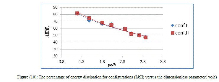
| The percentage of energy dissipation for configurations I (inclined on all steps ) and configuration II (endsills on all steps) is shown in figure (10) below. It can be observed a convergence of relative energy dissipation values on high dimensionless parameter (yc/h) (high discharge), but with reduction the dimensionless parameter (yc/h) the higher value of relative energy dissipation is for configuration II. It’s worth mentioning that the inclination of step result in a water trap with a recirculation pool, while the endsills increases the depth of the hydraulic jump at the step edge. |
 |
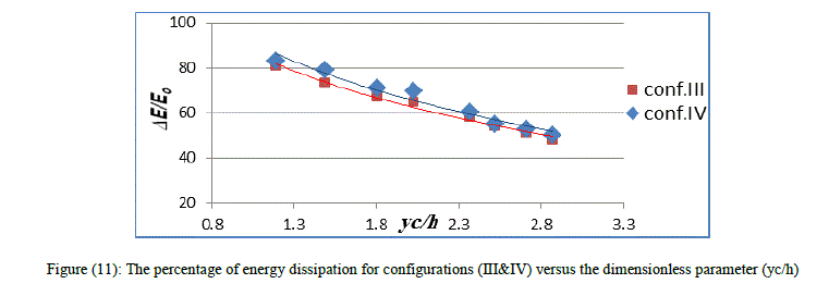
| Figure (11) shows the percentage of energy dissipation for configuration III (alternative endsills and horizontal steps) and configuration IV (alternative inclines and horizontal steps). The results indicated that, the configuration IV dissipate energy more than configuration III about (6.5% at q=0.02119 m3/s/m), this occurs when the air cavities are rapidly filled with water for free circulating between two steps for high discharge and to high air interment occurs especially on lower discharge. |
 |
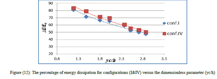
| When comparing the percentage of energy dissipation for configurations I (inclined on all steps) and configuration IV(alternative inclines and horizontal steps) in figure (12). It can be observed a high dissipation rate on configuration IV (about 5.5%), It is judged that for the free flow circulating between two steps. This configuration represented a mixture between the case of conventional and steps with inclined form, therefore, this increase of head loss may be attributed to the successive widening and narrowing of the flow caused by the passage from one step with inclined to the other step without inclined. |
 |
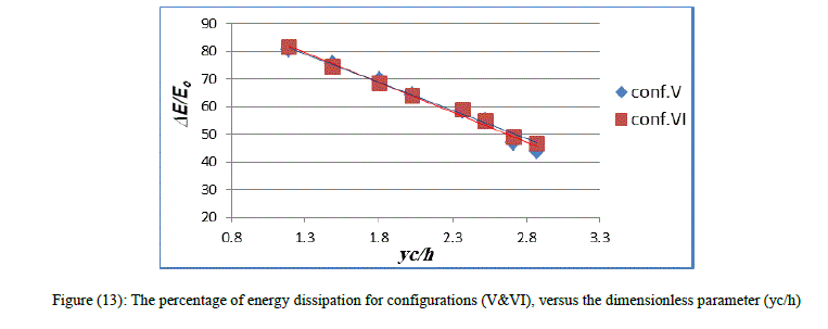
| To examine the effect of the shape of first step on energy dissipation rate, figure (13) shows the percentage of energy dissipation for configurations V (combined of inclined and endsills start with inclined steps) and VI (combined of endsills and inclined start with endsills steps). The results show that there are a little difference between them which can be negligible, just a little high in energy dissipation on first two runs in configuration VI. |
 |
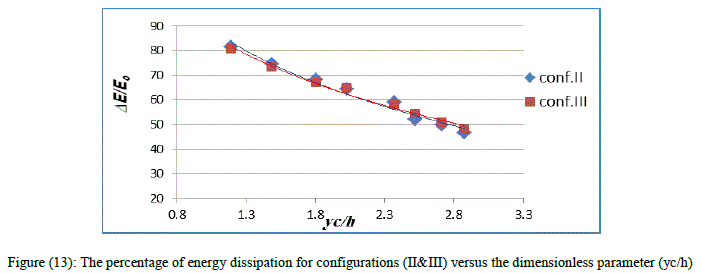
| Also, the experimental results for the percentage of energy dissipation of configuration II (endsills in all steps) and configuration III (alternative endsills and horizontal steps) as shown in figure (13), indicated that there is no significant difference between the two configurations. This result for high efficiency of configuration III to dissipate the energy, for development the recirculating cells inside the step cavity which was filled with water. |
 |
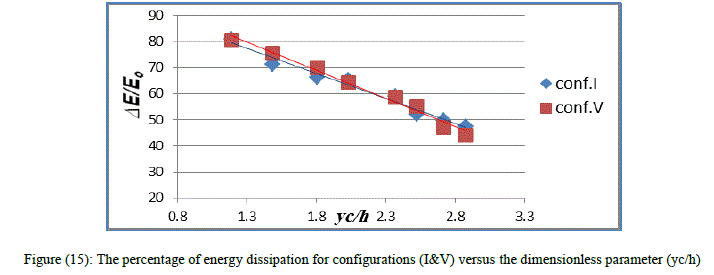
| But in Figure (15) which is showed the percentage of energy dissipation for configuration I (inclined on all steps) and configuration V (combined of inclined and endsills start with inclined steps), it can be seen the increasing in energy dissipation in configuration V than configuration I, though not great. This increasing in configurations (V&VI) is a result of increased the drag form, by transverse jet and wakes created by compound end sill and inclined together. |
 |
| To compare the energy dissipation obtained from these configurations with the energy dissipation obtained from a conventional type of stepped spillway the result is shown in figure (16) below. |
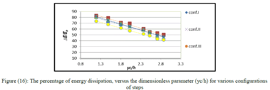 |
| It can be seen that the relative energy dissipation is increased in all configurations than the relative energy dissipation in conventional steps, for the reason explained above. The results indicated also that among test configurations, the highest energy losses is in configuration IV (inclined every two steps), this configuration is dissipated up to about (18.6 %) than conventional steps. |
VI. CONCLUSIONS |
| 1. In case of using different types of steps, i.e.(reverse inclined step, end sill ,reverse inclined steps and end sill together, alternative inclined and horizontal steps, alternative end sill and horizontal steps), those shapes have the most influence on the amount of the energy losses, it was increasing in energy losses by about (1.6%-18.6%) at different runs and configurations in comparison of horizontal steps. |
| 2. The inclined steps affects slightly on lower limit of skimming flow regime in comparison with horizontal steps, it increased slightly at some lower discharge, and there is no effect observed at higher discharge. |
| 3. The energy dissipation rate at configuration IV (alternative inclined and horizontal steps) show increase by about (6.2% at q=0.02119 m3/s/m) more than configuration III (alternative endsills and horizontal steps), and about (5.3% at q=0.02119 m3/s/m) more than configurations I (inclined on all steps) |
| 4. The results indicated that among test configurations, the highest energy losses is in configuration IV (inclined every two steps), it is increased in the energy dissipation rate by about (18.6 %) at (q=0.02119 m3/s/m). |
References |
|