ISSN ONLINE(2319-8753)PRINT(2347-6710)
ISSN ONLINE(2319-8753)PRINT(2347-6710)
Omkar Yarguddi1, Dr. Anjali A. Dharme2
|
| Related article at Pubmed, Scholar Google |
Visit for more related articles at International Journal of Innovative Research in Science, Engineering and Technology
Fuel cells directly and efficiently convert chemical energy to electrical energy. During the last decade, fuel cells have received enormous attention from research institutions and companies as novel electrical energy conversion systems. In the near future, they will see application in automotive propulsion, distributed power generation, and in low power portable devices (battery replacement). This review talks about the different types of fuel cells and their fundamentals. Various characteristics of the different fuel cell types such as operating temperatures, efficiencies, are compared
Keywords |
| Fuel cell, energy conversion, efficiency, characteristics |
I. INTRODUCTION |
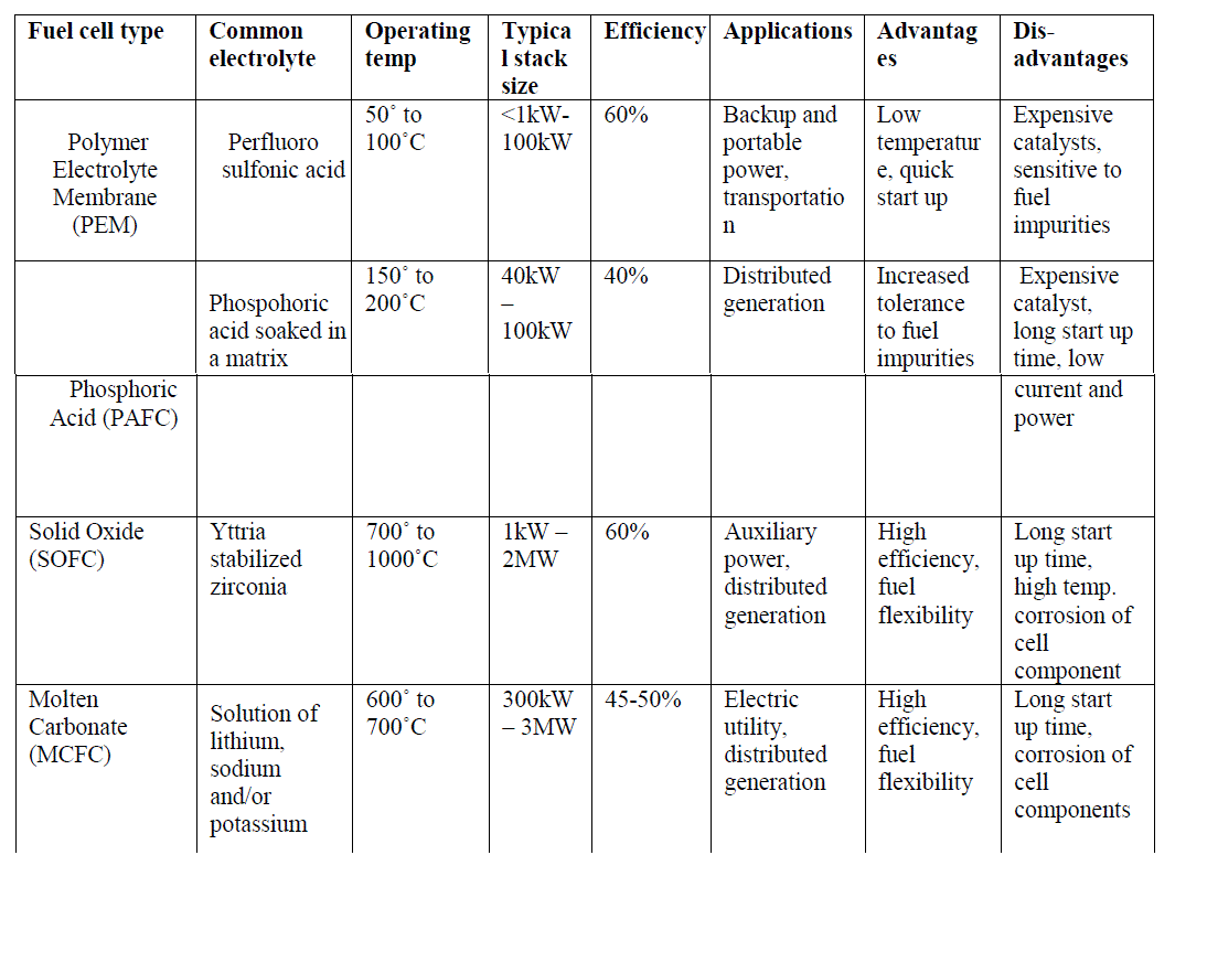
| Fuel cells are one of the most promising sources of renewable energy and can be considered as clean energy sources because of their low sulphur and nitrogen oxide emissions and low noise level operation. In addition, they are more efficient as compared to the conventional power sources as their efficiencies are not limited by the Carnot cycle. A fuel cell operates like a battery, but does not need to be recharged and gives continuous power when supplied with fuel and oxidant [1]. Attempts to develop fuel cells as power sources have been made over many years. Initially they were developed mainly for space and defence applications. However, the recent drive for more efficient and less polluting electricity generation technologies has resulted in substantial resources being directed into fuel cell development. Fuel cells, because of their high efficiencies, low noise and pollutant output, promise to revolutionize the power generation industry with a shift from centrally located generating stations and long-distance transmission lines to dispersed power generation at load sites [2]. Irrespective of the type of fuel cells, they all consist of an anode (negative side), a cathode (positive side) and an electrolyte that allows charges to move between the two sides of the fuel cell. Electrons are drawn from the anode to the cathode through an external circuit or load, producing direct current. As the main difference among fuel cell types is the electrolyte, fuel cells are classified by the type of electrolyte they use along with the difference in the time required for them to start ranging from 1 sec for Proton Exchange Membrane Fuel Cells (PEMFC) to 10 min for Solid Oxide Fuel Cells (SOFC). Fuel cells come in a variety of sizes. Individual fuel cells produce relatively small electrical potentials, about 0.7 volts, so cells are "stacked", or placed in series, to increase the voltage and meet an application's requirements [3]. Several fuel cell types are under various stages of development: Low temperature fuel cells such as the Solid Polymer Electrolyte Fuel Cell (PEMFC) and the Alkaline Fuel Cell (AFC) are mainly considered for transport applications. |
| The Phosphoric Acid Fuel Cell (PAFC), a medium temperature fuel cell, classified as first generation, has been developed to the most advanced stage. |
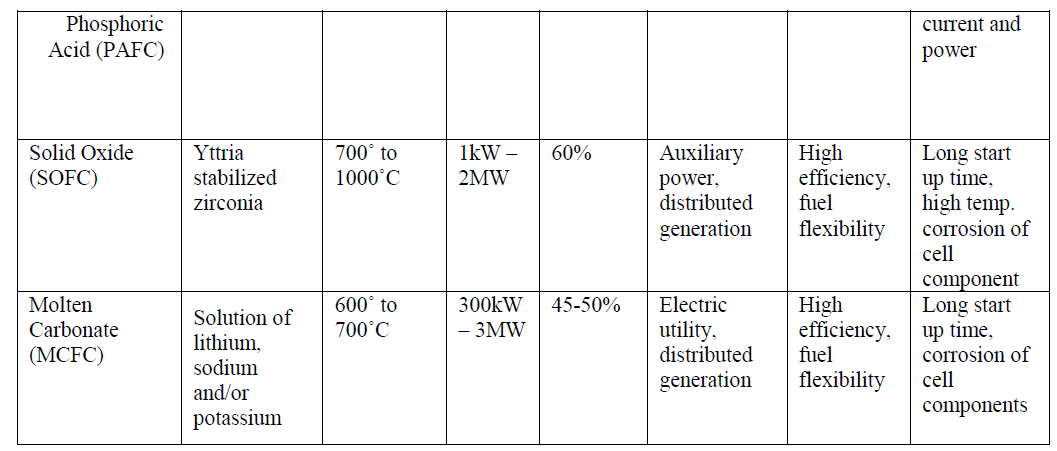
| The Molten Carbonate Fuel Cell (MCFC) is a high temperature fuel cell operating around 650°C and is known as a second generation fuel cell. Prototypes of MCFC in the 100 kW range are under construction and evaluation. The Solid Oxide Fuel Cell (SOFC), or third generation fuel cell, is attracting substantial interest as it is regarded as the most efficient and versatile power generation system, in particular for dispersed power generation. The current operating temperature is around 1000°C but substantial efforts are under way to reduce the operating temperatures to 800-900°C. |
II. PROTON EXCHANGE MEMBRANE FUEL CELLS (PEMFC) |
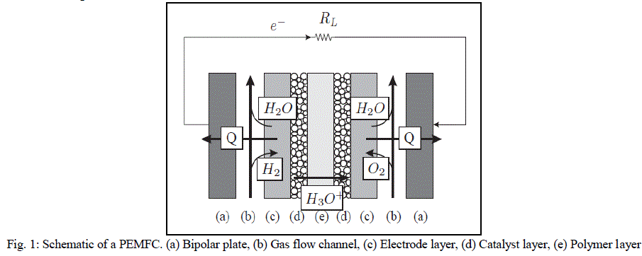
| A basic diagram showing the structure of the PEMFC is shown is Fig. 1. The main components are: (i) bipolar plates, (ii) electrodes, (iii) catalyst, (iv) membrane, and (v) the necessary hardware [4]. The materials used for different parts of the fuel cells differ by type. The bipolar plates may be made up of different types of materials, such as, metal, coated metal, graphite, flexible graphite, C–C composite, carbon–polymer composites etc. The membrane electrode assembly (MEA) is referred as the heart of the PEMFC and is usually made of a proton exchange membrane sandwiched between two catalyst-coated carbon papers. Platinum and/or a similar type of noble metals are usually used as the catalyst for PEMFC. The electrolyte could be a polymer membrane. |
| Air is fed to the cathodic layer, and hydrogen is fed to the anodic one. The central membrane which acts as the electrolyte also performs the function of reactant separation. On the anode side, hydrogen diffuses to the anode catalyst where it dissociates into protons and electrons. The protons are conducted through the membrane to the cathode, but the electrons are forced to travel through an external circuit (supplying power) because the membrane is electrically insulating. On the cathode catalyst, oxygen molecules react with the electrons (which have travelled through the external circuit) and protons to form water |
 |
| The electrochemical reactions involved are summarized below [1]: |
| H2 → 2H+ + 2e− (1) |
| 2H+ + 1/2O2 + 2e− → H2O (2) |
| H2 + 1/2O2 → H2O (3) |
| Equation (1) shows the anodic reaction, equation (2) shows the cathodic reaction, while equation (3) shows the complete cell reaction. |
| The main advantage of PEMFC is its high efficiency as compared to other conventional energy conversion devices [5]. Unlike internal combustion engines which have maximum efficiencies with high loads, fuel cell efficiency is high even with partial loads. This is particularly advantageous in automotive applications as the automobile generally demands only a fraction of the nominal fuel cell [6]. Thus, a fuel cell powered vehicle will be functioning at high efficiencies most of the time. Another important advantage of PEMFCs in contrast with the other fuel cell types is the relatively low operating temperature (below 80ÃÂC) [7], which allows them to reach the operating point quickly. In addition, the cost of materials used for construction of PEMFCs is generally lower in comparison with the high temperature fuel cell types, along with safer operation. |
| The main disadvantage is the overall high cost of the PEMFCs and the high production cost of Hydrogen as well as that of the platinum based catalyst. |
III. PHOSPHORIC ACID FUEL CELL (PAFC) |
| As the name suggests, in PAFCs, phosphoric acid is used as an electrolyte to allow passage of protons from the anode to the cathode. It is considered the first generation of modern fuel cells. PAFCs are similar to PEMFCs in the generalprinciple of operation: the hydrogen introduced at the anode is split into its protons and electrons. The protons migrate through the electrolyte and combine with the oxygen, usually from air, at the cathode to form water. The electrons are routed through an external circuit where they can perform useful work. This set of reactions in the fuel cell produces electricity and by-product heat. PAFCs work at a temperature levels between 150ÃÂ and 220ÃÂC. PAFCs |
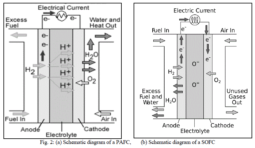 |
| operate with efficiencies of about 40-50% while generating. This efficiency can be improved to 80% using the heat generated for cogeneration [8]. Figure 2 shows a schematic of a PAFC. |
| One advantage of the PAFCs, apart from their high efficiencies, is their tolerance to carbon monoxide (CO) buildup within the cell. At a temperature of 200ÃÂC they tolerate CO concentration of about 1.5 percent. PAFCs provide high quality DC power with high power density values. The key disadvantage of this type of fuel cells is the use of an acidic electrolyte which increases the corrosion or oxidation of components exposed to the phosphoric acid. |
IV. SOLID OXIDE FUEL CELL (SOFC) |
| Solid oxide fuel cells (SOFCs) use a solid material, most commonly a ceramic material called yttria-stabilized zirconia (YSZ), as the electrolyte. Because SOFCs are made entirely of solid materials, they are not limited to the flat plane configuration of other types of fuel cells and are often designed as rolled tubes. They require high operating temperatures (800–1000 °C) and can be run on a variety of fuels including natural gas. SOFCs have efficiencies of the order of 50% - 60% while converting fuel to electricity. In cogeneration applications, the overall efficiency could be of the order of 80% - 85%. Figure 2(b) shows the schematic diagram of a SOFC. |
| The electrochemical reactions involved are as follows: |
| 2 H2 + 2 O2- → 2 H2O + 4 e- (4) |
| O2 + 4 e- → 2 O2- (5) |
| 2H2 + O2 → 2 H2O (6) |
| Equations (4), (5) and (6) represent the anodic, cathodic and the cell reactions taking place in a SOFC respectively [9]. |
| Unlike other fuel cell types, the charge carrier in SOFCs is the oxygen ion (O2-). At the cathode, the oxygen molecules from the air are split into oxygen ions with the addition of electrons which are then conducted through the electrolyte and combine with the hydrogen ions at the anode to produce water while releasing 4 electrons. These electrons travel through the external circuitry giving rise to an electric current. |
| The high temperature operation of SOFCs offers significant advantages like high resistance to presence of sulphur in the fuels. Additionally, they are also not poisoned by CO which can even be used as fuel. This property of SOFCs allows them to use gases made from coal as fuels. The high operating temperature also removes the need of precious metal catalysts which are necessary in the low and medium temperature fuel cells, thereby reducing cost. Since the electrolyte is solid, the orientation of the fuel cell can be according to the requirements of the application thereby giving rise to modular designs [10]. Disadvantages include high starting time due to the high operating temperature. |
V. MOLTEN CARBONATE FUEL CELLS (MCFC) |
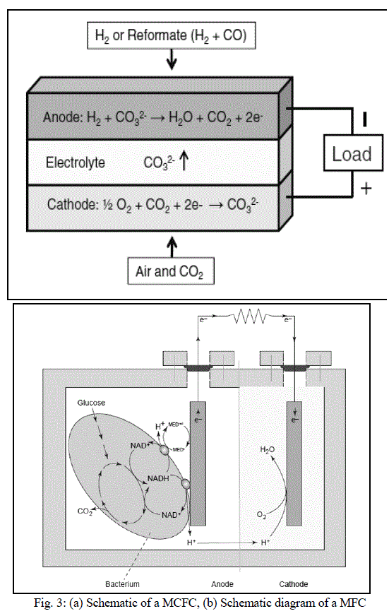
| MCFCs are different as compared to other fuel cells in that they use an electrolyte composed of a molten carbonate salt mixture suspended in a porous, chemically inert ceramic lithium aluminium oxide (LiAlO2) matrix. To achieve melting of the carbonate salts and high ion mobility, the operating temperature of the fuel cells is high (around 600ÃÂC - 700ÃÂC) [11]. At this temperature range, the salts melt and become conductive to the carbonate ions. These ions travel from cathode to anode where they combine with hydrogen to give water, carbon dioxide and electrons. These electrons travel through an external load giving rise to an electric current, and return to the cathode. At the cathode, oxygen from the air and carbon dioxide recycled from the anode react with the electrons to form carbonate ions that replenish the electrolyte, completing the circuit [12]. Figure 3(a) shows a schematic of a MCFC. The electrochemical reactions are summarized below: |
| H2 + ½O2 → H2O (7) |
| CO2 + ½O2 + 2e− → CO32− (8) |
| CO32− + H2 → H2O + CO2 + 2e− (9) |
| Equations (7), (8) and (9) represent the anode, cathode and overall cell reaction taking place in a MCFC respectively. Like SOFCs, MCFCs are capable of converting fossil fuels to hydrogen rich gases owing to their high operating temperature |
| Therefore, a variety of fuels such as natural and coal gases can be used. MCFCs also show resistance to fuel cell poisoning due to CO which makes coal gases an attractive choice for fuel. MCFCs when coupled with turbines can reach efficiencies approaching 65%.When the waste heat is captured and used (i.e. in cogeneration), the efficiency can be improved to 80% [13]. |
| The disadvantages of MCFCs include slow start-up times because of the high operating temperatures, and the comparatively short life-spans. The high temperature and the molten carbonate electrolyte cause corrosion of the electrodes causing significant reduction in the operating life. |
VI. MICROBIAL FUEL CELL (MFC) |
| A MFC converts energy, available in a bio-degradable substrate, directly into electricity. This can be achieved when bacteria switch from the natural electron acceptor, such as oxygen or nitrate, to an insoluble electron acceptor, such as the MFC anode. The electrons then flow through a resistor to a cathode, at which the electron acceptor is reduced. As opposed to anaerobic digestion, a MFC creates electric current and an off-gas containing mainly carbon dioxide [14]. Figure 3(b) shows a schematic diagram of a MFC [15]. |
| Bacteria require energy for their growth which they get in a two-step process. The first step requires the removal of electrons from some source of organic matter (oxidation), and the second step consists of giving those electrons to something that will accept them (reduction), such as oxygen or nitrate. If certain bacteria are grown under anaerobic conditions (without the presence of oxygen), they can transfer electrons to a carbon electrode (anode). The electrons then move across a wire under a load (resistor) to the cathode where they combine with protons and oxygen to form water. When these electrons flow from the anode to the cathode, they generate the current and voltage to make electricity. [16] |
| Advantages of MFCs include the use of a wide variety of organic materials as fuels, as well as their efficient operation at ambient and low temperatures distinguishing them from the current bio-energy processes. Low power densities as compared to other technologies puts this technology at a slight disadvantage. |
 |
 |
 |
VII. CONCLUSION |
| The recent thrust in development of clean and renewable energy sources has brought the fuel cell technology in the limelight. Now being looked upon as clean energy sources, fuel cells have the potential to revolutionize the domain of energy generation. To increase the share of fuel cells in the power generation scenario, significant improvements are needed. Provided electrochemical technology advances, the overall catalyst and electrode prices decrease, fuel cell technology may qualify as a new core technology for conversion of chemical energy to electricity and open up new vistas for utilization of previously untapped sources for electricity generation. |
ACKNOWLEDGMENT |
| The authors are grateful to the organizers of NCMEA 2014 at College of Engineering, Pune. The authors would also like to thank Prof. Dr. D. B. Talange and Prof. Dr.V. S. Bandal for their inputs. |
References |
|