ISSN ONLINE(2319-8753)PRINT(2347-6710)
ISSN ONLINE(2319-8753)PRINT(2347-6710)
Kanteyya A1, Kiran Kumar Rokhade 2
|
| Related article at Pubmed, Scholar Google |
Visit for more related articles at International Journal of Innovative Research in Science, Engineering and Technology
The flow field in the hyperbolic natural draft wet-cooling tower, which has great effects on the economy and security of power plant, was studied through numerical simulation. The mathematical model was established and analysed in order to optimize the cooling-tower and to evaluate its efficiency and a Numerical study on a channelchimney system was carried out in order to elucidate the behaviour of heat transfer and fluid flow. A 2D CFD model of natural draught Cooling tower and chimney like heat sink plate is developed the Euler multiphase model was used to simulate the heat and mass transfer in a natural draught cooling tower rain zone and the RNG turbulent model with the dispersed option is used for the turbulence modeling of multiphase flow. The results are presented in terms of local air temperature measurements inside the symmetrically heated channel and between the adiabatic extensions.
Keywords |
| Cooling tower, Chimney, static pressure, CFD. |
INTRODUCTION |
A) Cooling Tower: |
| Cooling-tower is of great importance in equipping power plants which can reduce the temperature of circulating water through heat and mass exchange and release the heat that stems from condenser to the environment with a high efficiency [1]. Materials for cooling tower in nuclear power plant used as structural steel |
B) Chimney: |
| Natural convection is an energy transport process that takes place as a result of Buoyancy-induced fluid motion occurring in the presence of a body force field. According to the author Mohiuddin & Kant [2] were described a detailed methodology for the thermal design of wet, counter flow and cross flow types of mechanical and natural draught cooling towers. According to the author Chu & Rahman [3] presented an initial report on a single data point each for configurations of with and without-wire mesh chimney adaptor, at a nominal heat load of 2.35 kW of an air cooled heat exchanger model, showing a draft enhancement of 45% by the configuration fitted with the wire mesh chimney adaptor. Materials for chimney steel is used or some time sand and bricks are used |
| C) Methodology: 1) Pre Processing Consisting in the construction of geometry, the generation of the mesh on the surfaces or volumes. For 2D there are mapped meshes of quadrilateral faces and other faces easier to develop like the triangles |
| 2) Definition of boundary conditions and other parameters, initial conditions, before starting a simulation in FLUENT, the mesh has to be checked and scaled and modified if necessary. This includes the choice of compressibility, viscosity, heat transfer considerations, laminar or turbulent flow, steady or time dependent flow. |
| 3) Resolution of the problem, which is done through iteration until the convergence of the variables is obtained. First of all, the variables of the flow have to be initialized and set to be computed from a certain part specified by the user |
| 4) Post Processing or analysis of the results computed. There are lots of choices: Contours, X-Y plots, velocity vectors, path lines. In them, several variables can be analysed: velocity, pressure, turbulence, forces, density and others. |
II. OBJECTIVES OF THE PRESENT STUDY |
| ï§ To determine average heat and mass transfer coefficients |
| ï§ To examine the effect of various parameters such as feed flow rate, air flow rate, inlet water temperature, enthalpy, thermal conductivity, density, turbulent viscosity etc. on the performance of the cooling tower. |
| ï§ Study on a channel-chimney system was carried out in order to elucidate the behaviour of heat transfer and fluid flow. |
| ï§ Different fluid motion regions are observed inside the chimney. Inflows of air are detected in the lower extension ratio, particularly for large values of the ratio of the width of chimney to that of the heated channel |
III. FLOW DIAGRAM FOR THE REPRESENTATION OF ANALYSIS METHODOLOGY |
| Consisting in the Construction of geometry, the generation of the mesh on the surfaces or volumes. This stage is done with the software Hyper Mesh, linked to FLUENT. The geometry can be also imported from other CAD software’s like CATIA. For creating the mesh there are different options that Hyper Mesh provides. |
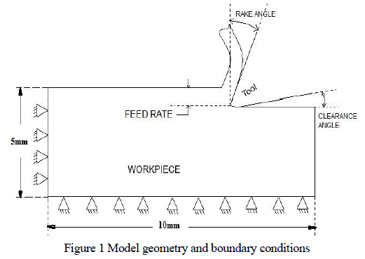 |
| For 2D there are mapped meshes of quadrilateral faces and other faces easier to develop like the triangles |
IV. BASIC STEPS IN CFD ANALYSIS |
| ï§ Problem Identification and Pre-Processing |
| 1. Defining model. |
| 2. Identifying the domain. |
| 3. Design and creation of the grid |
| ï§ Solver Execution |
| 1. Set up the numerical model. |
| 2. Compute and monitor the solution. |
| ï§ Post-Processing |
| 1. Examine the results. |
| 2. Consider revisions to the mode |
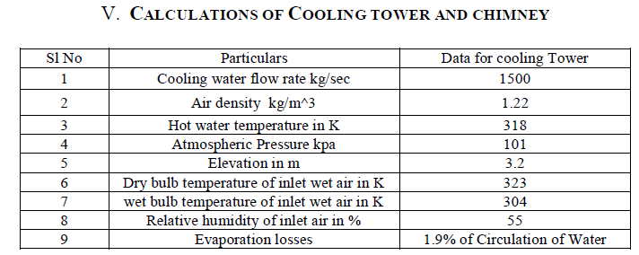 |
| Table 1: Inlet Water Condition for Cooling Tower |
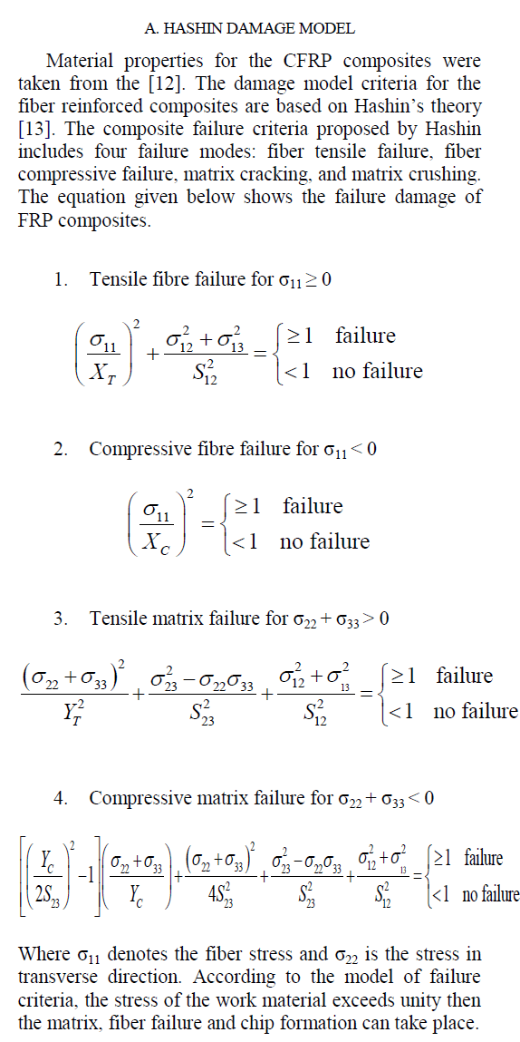
| The rate of heat removed from the water is equal to the rate gained by the air, so the following expression can be written |
 |
VI. GEOMETRY DETAILS FOR COOLING TOWER AND CHIMNEY |
 |
VII. BOUNDARY CONDITIONS |
A) Cooling Tower: |
| Velocity inlet boundary condition is used to define the inlet velocity and other properties of air. Velocity magnitude of air takes normal to the boundary of inlet and turbulence is taken as intensity and length scale. Thermal condition and species in mole fraction is defined. The Pressure out let is defined at the out let of the air and other zone is also defined likewise. In cell zone surface body is considered as fluid and the operating pressure is 101.325 Pa in upstream from the centre line of the cooling tower. The gravitational acceleration is 9.81 m/s2. Operating temperature is 298.16 K and operating density is 1.22 kg/m3 entered |
B) Chimney heat sink: |
| The boundary conditions for the 2-dimensional heat sink we concerned are: constant wall temperature Tw at 400K, constant distance of the parallel plate’s b at 0.04m. The fluid around the heat sink is air with constant Prandtel number at 0.74, and temperature T∞ at 300K, density ρ=1.22kg/m3,zero gauge pressure and velocity is consider as 1m/s. |
VIII. RESULT AND DISCUSSION |
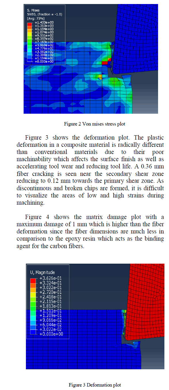
| A) Cooling tower: The contours of static temperature of the air. The air which is having ambient temperature entering in to the cooling tower and suddenly changes the temperature due to contact of hot water coming out from the nozzle. The fig 3(a) shows highest temperature zone is near the middle axis of the cooling tower i e. in between the vertical axis and cooling tower wall. As the air flows up the temperature goes decreases and near the wall of cooling tower the air temperature is reduces. |
 ` ` |
| The pressure is constant through-out the wall of cooling tower as shown in fig 3(b) and below the fill it is always higher than above the fill. The dynamic pressure is having higher value near the wall of cooling tower and lesser value near the vertical axis of cooling tower height |
 |
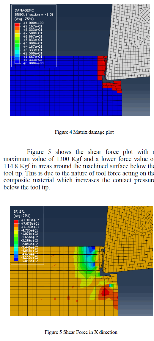
| For analysis of thermal performance three lines have been drawn as near axis (shown in fig 4a), near wall and between axis and wall. Temperature is having its high value in middle line 318 K and lower near the wall 307 K because in middle the air is contact with more hot water coming out from the nozzle. The total pressure is suddenly falls from 7 Pa to 0 Pa at fill area and then slight increases according to the height of Cooling tower and the density is high near the wall of cooling tower (shown in fig 4b).The thermal conductivity of fluid is 1400 W/m-k at the axis of cooling tower because of high temperature and low density. The Turbulence intensity is changing randomly up to the12m and then takes its smooth values (as shown in fig 4c). |
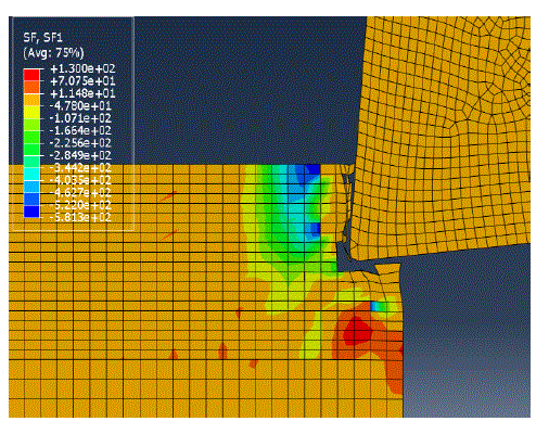
| B) Chimney like Heat Sink: By observing the blow fig 5a, 5b and 5c show the temperature profile, pressure and velocity profile changes at the wall side this due to 3 terms i.e. expansion ratio, Channel extension ratio and mass flow rate |
 |
| From fig 6a shows the heat flows along the unheated wall. The heat diffusion towards the colder ambient air close to the outlet of the chimney, from the fig 6b the velocity at the outlet of the channel is more than the centre of the channel because of high heat sink width. The edge effects more convection than the centre of the channel but the velocity of the channel is remains constant and the pressure is decreases because of an increase in height of the plate. The channel extension ratio is L/Lh = 3.0 and expansion ratio is B/b = 3.0. The temperature at the edge, pressure at the inlet and velocity at the outlet of the channel is 345.624 K, 0.676 Pa and 1.084 m/s respectively this at the seventh model. |
 |
IX. CONCLUSION |
| By conducting two dimensional CFD simulations for investigating the thermal performance of wet cooling tower the overall changes take place in three zones. |
| ï§ The thermal conductivity of the fluid is more in the vertical axis of cooling tower. |
| ï§ The Density of fluid is having reciprocal values of input temperature. |
| ï§ The Enthalpy of fluid is low at the wall of cooling tower. |
| ï§ Turbulent intensity is increases up to rain zone and then decreases, turbulent viscosity decreases up to fill zone and then increases. |
| ï§ Stream function is linearly constant for axis and decreases according to height for middle line and line near wall. Enthalpy decreases after rain zone and its value is low near the wall area. |
References |
|