ISSN ONLINE(2320-9801) PRINT (2320-9798)
ISSN ONLINE(2320-9801) PRINT (2320-9798)
V.Suresh1, V.K.Gopperundevi2, Dr.A.Abudhahir3, R.Antonysamy4, K.Muthukkutti5
|
| Related article at Pubmed, Scholar Google |
Visit for more related articles at International Journal of Innovative Research in Computer and Communication Engineering
Many applications involve the generation of homogenous and controlled magnetic field such as spacecraft, magnetic resonance imaging, Bioelectromagnetics research and NDT. Coil design is the prime factor for magnetically controlled device. In the design of the coil, the computation of magnetic field is the important task and there are several methods exists to compute the magnetic flux distribution like analytical method and numerical method. Numerical methods are boundary element method and finite element methods. Those numerical methods depend on discretization of analyzing region and it is a time consuming process. On the other hand, analytical methods are used commonly for the computation of magnetic field due to its simplicity. The main objective of the paper is to obtain the analytical expression for the calculation of radial and axial magnetic field component created by an iron core solenoid and the bobbin coil arrangement. The analytical expressions to compute the magnetic field at off axis point for the coil wounded on ferromagnetic material and bobbin coil arrangement are obtained. The obtained analytical expressions are based on vector potential. FEMM 4.2 software is used for numerical analysis. The obtained analytical expressions are based on elliptic integrals and the results are calculated using MATLAB. Accuracy is investigated by comparing the analytical results with the simulation results.
Keywords |
| Bobbin coil, analytical expression, elliptic integral,vector potential , FEMM, MATLAB. |
INTRODUCTION |
| The electromagnetic coil is very important in sensors and modern medical and electric systems. Magnetic field computation is the prime task in the coil designs. Analytic methods and numerical methods are used to analyze the magnetic field distribution. Boundary element method and finite element method are the common numerical methods employed, but these numerical methods are time consuming process. On the other hand analytical methods are simple to obtain. Analytical Methods are important to understand the existing knowledge and to extend that knowledge within the limits of the critical bounding assumptions. Different analytical methods to determine magnetic field density are as follows: Biot Savart law, Magnetic Vector Potential, Magnetic Scalar Potential and Coulomb’s law. All the models are directly derived from Maxwell’s equation [1]. |
| Analytical approaches are very important for the design of many devices. This paper presents the method for calculating the magnetic field created by solenoid of finite length. In this paper, the cylindrical solenoid is considered. The method of calculation is based on vector potential. An analytical expression for solenoid of various geometries were derived using the magnetic dipole method and the expression is validated through conventional expression [2]. Gauss Legendre numerical integration tool was involved to derive the analytical expression for coil with rectangular cross section [3]. The Green function approach was used to derive the analytical expression for magnetic field created by cylindrical coil and the correlation between the cylindrical coil and axially magnetized permanent magnet of ring shape is achieved [4-5]. Elliptical integral based expression was developed for single turn circular coil [6]. |
| In the proposed method, vector potential based two dimensional analytical expression for the solenoid is derived following that, the analytical expression for the magnetic field is derived for coil wounded on iron core and bobbin coil arrangement. . The entire calculations involve integration of simple functions. However, the mathematical relations are not directly defined from the integral function but by using certain modifications, expressions are obtained. Finally, this paper involves the analytical expression for the bobbin coil arrangement. Bobbin structure can be viewed as three parts, the center part is the coil which is wounded on ferromagnetic material and the projections on either side of the center part, the projections are viewed as permanent magnets. |
| Three dimensional expression was formulated for radially magnetized permanent magnet of ring shape. The effect of outer face of the permanent magnet was neglected to simplify the calculation [7]. This paper involves the cylindrical shaped bobbin structure. The focus of the method is to calculate the magnetic field distribution at any point on the surface closer to bobbin structure. The obtained expression is simple when compared to the expression computed for ring shaped permanent magnet. The obtained expressions involve elliptic integrals and heumann lambda function. The calculated values are compared with the simulated result.Simulation is performed on FEMM 4.2 version [10]. |
II. SPECIAL FUNCTIONS |
 |
III. MAGNETIC FIELD PRODUCED BY COIL |
A. Solenoid |
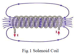
| A solenoid is a coil wound in a helical manner, which can be used to generate a nearly uniform magnetic field similar to that of a bar magnet, when an electric current is passed through it [8]. Solenoids are important because they can create a controlled magnetic field and it can be used as electromagnets. The term solenoids refers specifically to a coil designed to produce a uniform magnetic field in a volume of space inside it. The orientation of magnetic field lines produced by a solenoid coil is shown in Fig.1. They have an enormous number of applications. |
 |
| B. Analytical methods |
| The existing methods to compute the magnetic field distribution are Biot-Savart law, Magnetic Vector Potential, Magnetic Scalar Potential and Coulomb’s law. |
| Biot-Savart law states that “the magnetic field density of a current element at any point in a magnetic field is directly proportional to the current element and inversely proportional to the square of the distance between the current element to that point” and the formula for magnetic field density is given by equation (4) |
| Generally when dealing with analytical expressions of magnetic field distribution in coils, vector potential is used. The expression for vector potential is given in equation (5) |
| The prevalent method used in the literature to determine the flux density for magnets is the calculation of the scalar potential. The expression for scalar potential is given in equation (6) |
| Where define the observation point, define the position of the elementary source on the charge surface, s+ is the positively charged surface and s- is the negatively charged surface. This calculation represents the magnetic source by charge surface densities. The total scalar potential is calculated by the application of superposition principle. The magnetic field is then calculated by, |
| The other way to calculate the magnetic field created by the magnet is to use coulomb’s law directly. Though this method is developed for magnets it can also apply to coil also. With the charged plane model the magnetic field, is calculated first and from which flux density, can be deducted. The expression for magnetic field intensity is given by equation (8). |
| C. Vector potential expression |
| The Gauss law of magnetism states that magnetic field density can be expressed as the curl of the vector field. The vector field is called as vector potential and it is denoted by A. |
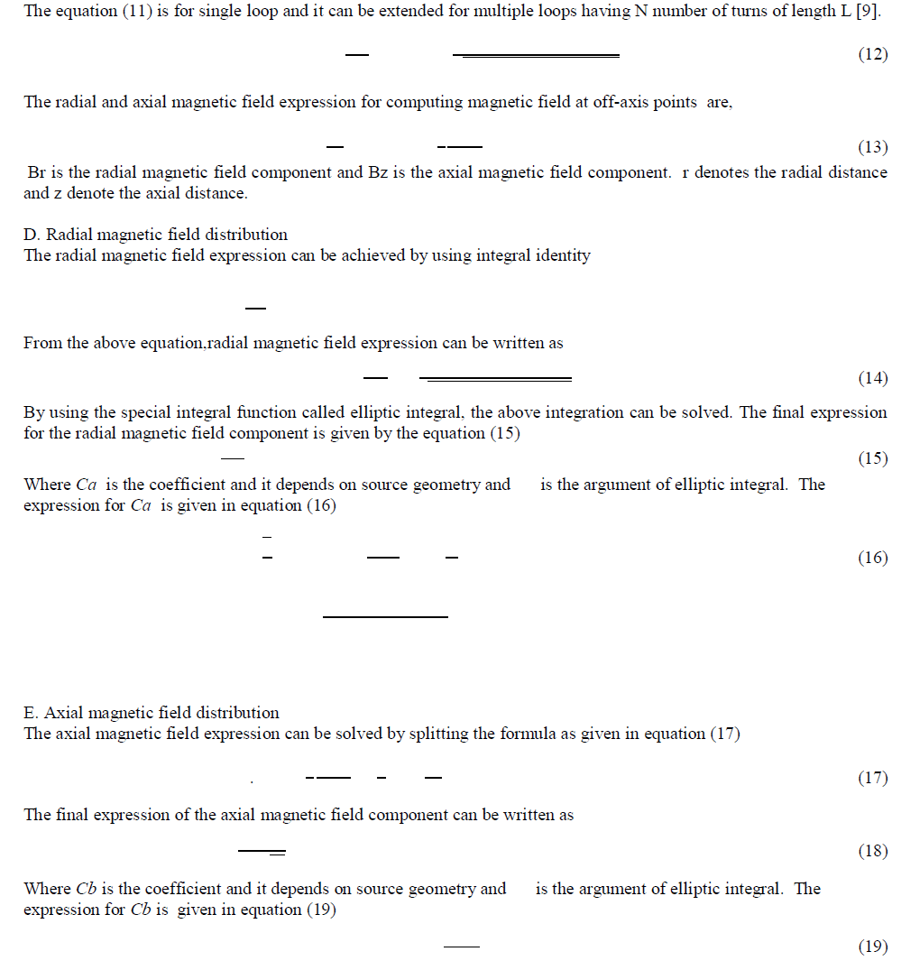
| The expression for magnetic field distribution in solenoid can be achieved by means of magnetic vector potential. This section begins with the vector potential expression for single loop of radius R. Cylindrical coordinate system is adopted here. The center of the loop coincides on the z axis and the loop is parallel to x-y plane with the distance l from the x axis, the vector potential at point P (field point) in the xz plane with the coordinates (r,0,z) . |
| Vector potential expression for the single loop is given by |
| Due to the geometry, ds can be written as |
| The vector potential for single loop can be written as |
| The first term in the equation (10) vanishes and switching to cylindrical coordinate system, the resultant expression is |
 |
IV. MAGNETIC FIELD PRODUCED BY IRON CORE SOLENOID |
| The analytical expression for the iron core solenoid is derived as same as the air core solenoid. The field produced by the solenoid can be strengthened by the addition of the iron core. This section presents the analytical expression for iron core solenoid. The main cause for an increase in the field strength is the permeability of the material. The permeability of the material is nonlinear, it takes different values at each point, hence for the calculation purpose the permeability of the material is assumed to be constant. The value of permeability is taken from the BH curve of the material used. |
| At the saturation point of BH curve, the value of magnetic flux density and field intensity values are taken from which the value of is calculated. |
 |
| Where R’ is the radius of the core material μ is the permeability of the material used.r is the radial distance and z is the axial distance. L is the length of the wounded coil, N is the number of turns, I is the source current. Br and Bz denotes the radial and axial magnetic field density component. |
V. MAGNETIC FIELD PRODUCED BY BOBBIN COIL |
| A bobbin coil arrangement is the most widely used arrangement in MFL technique. It consist of a coil that is wounded on a housing. The structure of the housing is similar to a seamstress’s bobbin used for sewing thread. Because of the structure, it can produce higher flux density than the air core solenoid and iron core solenoid. This section presents the analytical expression of magnetic field density for bobbin coil arrangement. The structure of bobbin coil is shown in the Fig. 2. |
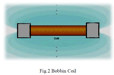 |
| To obtain the analytical expression for magnetic field created by bobbin, the structure of the bobbin is decomposed into three parts. The middle part resembles the iron core solenoid, since the coil is wounded in this portion. And the other two parts are the projections which are present on either side of the middle portion i.e., iron core solenoid, resembles the cylindrical permanent magnet. Hence in the given below magnetic flux density expression the first part denotes the magnetic flux density due to iron core and the second part denotes the magnetic flux density due to the two cylindrical permanent magnets. |
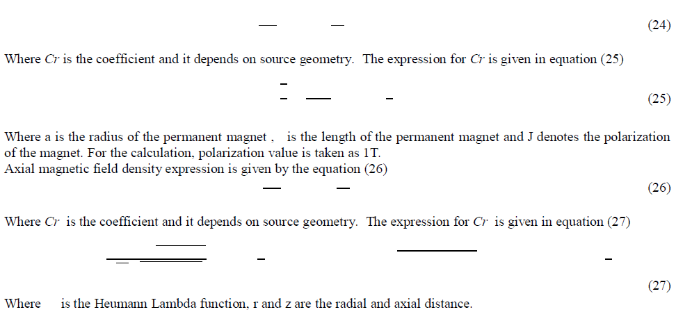
| The radial magnetic field density expression is given by the equation (24) |
 |
VI. RESULTS AND DISCUSSIONS |
A. IRON CORE SOLENOID |
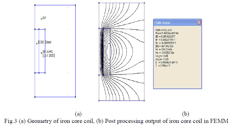
| The field produced by the air core solenoid can be strengthened by the addition of the iron core. Dimensions of iron core solenoid used in the analytical calculation and FEMM 4.2 simulation software [10] are inner diameter =5mm, outer diameter =12mm, core length =20mm, number of turns=100, 18 AWG copper wire, source current=1A. The geometry of iron core solenoid and post processing output of the same is shown in Fig 3(a) and (b). The steel 1010 is used as the core material and the permeability of the material is 7.8005×10⁻⁶ H/m. The material is consider as linear and the permeability value is taken from the BH curve at the saturation point. The magnetic field density are calculated using the proposed method and FEMM 4.2 software. |
 |
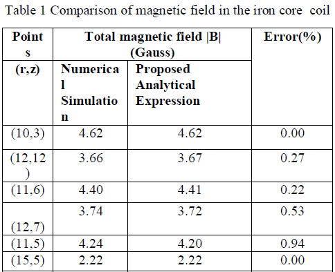
| Table 1 shows the result of total magnetic field for proposed analytical expression and numerical simulation. The results are in good aggrement with each other. |
 |
B. BOBBIN COIL |
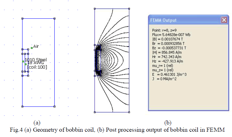
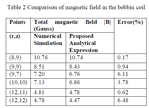
| A bobbin coil arrangement is the most widely used arrangement in MFL technique for magnetizing the pipe wall. It consist of a coil that is wounded on a housing. The structure of the housing is similar to a seamstress’s bobbin used for sewing thread. The bobbin coil is viewed as three parts, the middle part resembles the iron core solenoid, since the coil is wounded in this portion. And the other two parts are the projections which are present on the either side of the middle portion. In this work, projected regions are considered as cylindrical permanent magnet. The geometry of bobbin coil and post processing output of the same is shown in Fig 4(a) and (b). The magnetic field density is calculated using the proposed method and FEMM 4.2 software. Table 2 shows the comparison of analytical and simulation results of bobbin coil arrangement. |
 |
 |
VII. CONCLUSION |
| The analytical expression for radial and axial magnetic flux density component in iron core and bobbin coil arrangement are proposed. The proposed analytical expressions for magnetic flux density involves elliptic integrals and it is computed easily by means of MATLAB. The numerical simulation of both arrangements was simulated using FEMM 4.2 software. The validation was done by comparing the analytical results and simulation results. The analytical expressions of magnetic flux density obtained for the iron core solenoid is well correlated with the simulation results. The analytical expressions of magnetic flux density obtained for bobbin coil arrangement is work well at the center part of the bobbin. In the projected region of the bobbin, the error is high. |
References |
|