International Journal of Innovative Research in Science, Engineering and Technology
ISSN ONLINE(2319-8753)PRINT(2347-6710)
ISSN ONLINE(2319-8753)PRINT(2347-6710)
V. Nikooei1, A. Bakhshali Pour2
|
| Related article at Pubmed, Scholar Google |
Visit for more related articles at International Journal of Innovative Research in Science, Engineering and Technology
Airfoil Aerodynamic of the wind power turbines blade is of paramount importance on aerodynamic performance of wind turbines. This research includes a cross section choose of an airfoil employed in wind power turbine blades in the country. Here, the cross-section of 660 kW turbine blade, launched by the Vestas Company in Iran, has been modeled. Airfoil geometry was produced using the software ANSYS WORKBENCH, and has been analyzed fluidly via the software ANSYS FLUENT 15 across the angles of attack "-5" to "20" degrees and in the Reynolds digits ofô«. ô«ô« × ô«ô«ô«and ô«. ô«¡ô« × ô«ô«ô« along with applying Turbulent flow influence. The effects of Reynolds digits and increase of turbulence have been analyzed over the crossing points' situation. Furthermore, this part of turbine has been tested experimentally in Shiraz wind tunnel and the coefficients of lift, drag, and other properties have been studied in case
Keywords |
| Airfoil, Attack Angle, Lift Coefficient, Drag Coefficient |
INTRODUCTION |
| Due to the growing consumption of electrical energy and increase of the cost of fossil fuels as well as the environmental pollution, the use of new and recyclable energy, especially the wind energy to produce electricity is rapidly developing. Despite of the great potential for utilizing the wind energy as to produce electricity in Iran, there is not sufficient knowledge there so that, it is a good reason for the necessity and significance of this study [1]. |
| One of the most important factors to determine the power of wind power turbines is the profile type used in turbine. Besides, the performance of these turbines in the attack angles is high, so the available codes cannot predict the coefficients exactly; this causes a big difference between the power calculated via the software BEM using the results of available codes and the measured power. Given, the wrong calculation of aerodynamic forces attribute inappropriate impacts on the turbine structure, it is caused by underestimating the impacts of such various parameters and their sizes as roughness, turbulence, and the currency etc [2]. |
| Since the change of such parameters as the Reynolds number, angle of attack as well as the turbulence intensity of the flow are influential in the performance of a two-dimensional cross-section, installed on the blade of wind power turbines, so in this research, we simulated the aerodynamic behavior of a cross-section of the turbine blade, experimented in the low noise wind tunnel by Iranian expert in Jahad Research Institution of Fars Province using the software FLUENT software, and then compared the results obtained from the static tests with experimental results [3]. |
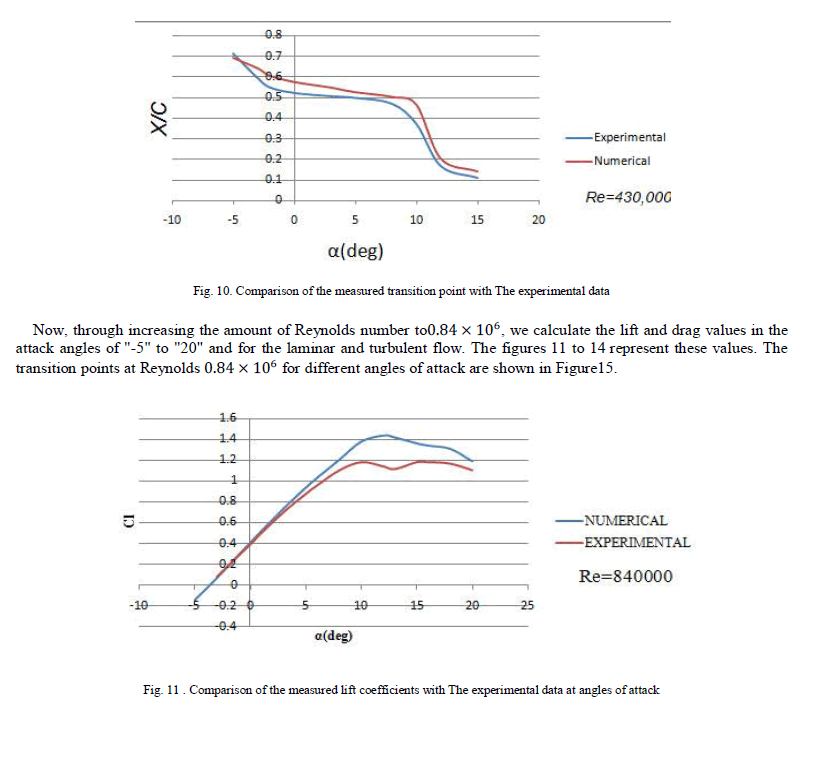
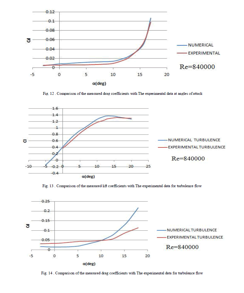
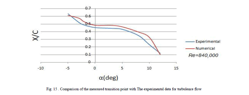
| The results showed that increase of the Reynolds number caused the aerodynamic performance of airfoil raised, also the change of Reynolds number and turbulent intensity brought about change in crossing point location. |
 |
II. LIFT AND DRAG |
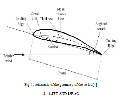
| An airfoil is defined as a cross of the body in the most efficient mode to produce the useful aerodynamic force against the airflow. Cross of wing, propeller's blades, windmills blades, compressor and turbine blades in jet engines and hydrofoils are all examples of the airfoil. The main geometry of an airfoil is shown in Figure. 1. |
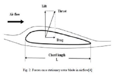
| Lift on a body is defined as the force on the body in a direction normal to the flow direction. Lift will only be present if the fluid incorporates a circulatory flow about the body such as that which exists about a spinning cylinder. The velocity above the body is increased and so the static pressure is reduced. The velocity beneath is slowed down, giving an increase in static pressure. So, there is a normal force upwards called the lift force. The drag on a body in an oncoming flow is defined as the force on the body in a direction parallel flow direction. |
| For a windmill to operate efficiently the lift force should be high and drag force should be low. For small angles of attack, lift force is high and drag force is low. If the angles of attack (α) increases beyond a certain value, the lift force decreases and the drag forces increases. So, the angle of attack plays a vital role.Lift and drag is presented in figure 2.[4] |
 |
MODELLING AND SIMULATION OF AIRFOIL |
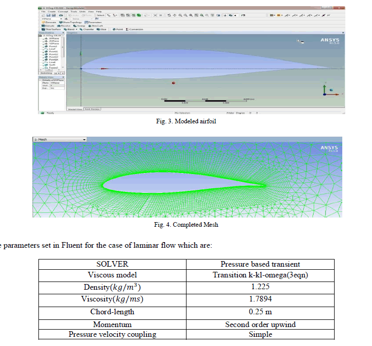
| The Airfoil examined in this study has been shown in Fig. 3. In order to analyze the current on blade, the wind turbine was meshed within the software ANSYS FLUENT 15. Fig. 4 shows the meshing on the airfoil. |
 |
AMOUNTS OF LIFT AND DRAG |
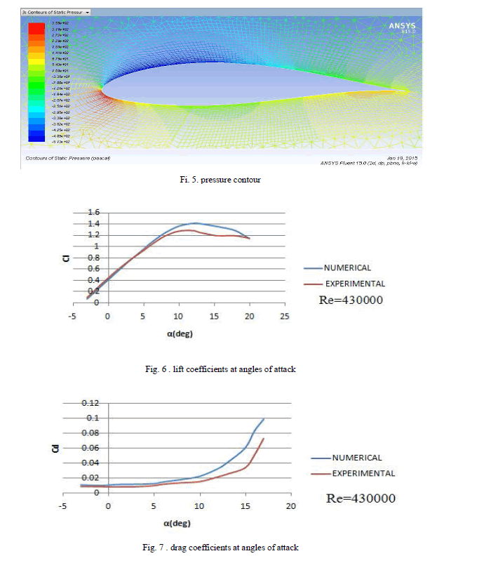
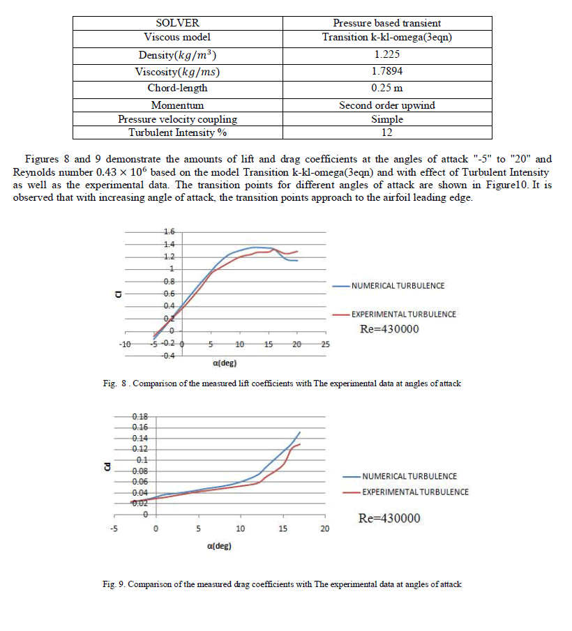
| The high-pressure area at the attack edge (stagnation point) and a low-pressure area in the upper surface of airfoil at a specified attack angle are observed on the pressure contour of Figure 5. The Bernoulli equation demonstrates that where there is a high speed, there would be less pressure and return. The Figures 6 and 7 indicate amounts of lift and drag coefficients at angles of attack "-5" to "20" and the Reynolds number 0.43 × 10��based on the model " Transition k-kl-omega (3eqn) " along with experimental data. |
| The algorithm automatically generates mask image without user interaction that contains only text regions to be inpainted. |
 |
| Now, we process the turbulence effect on the transition point by changing the current from laminar state to turbulent as well as changing fluent parameters. |
| The parameters set in Fluent for the case of Turbulent flow which are: |
 |
 |
 |
 |
CONCLUSION |
| Such factors as the atmosphere turbulence, finally causing the turbulence current, brings about decline in the producing power efficiency of the wind turbine, which is inappropriate impact. In order to stem these issues, firstly, the wind turbines must be posed in the flat locations and far from different obstacles and secondly, such airfoils with lower sensitivity towards the turbulent current effects, be utilized in design of their blades. |
| The difference between the experimental data and numerical values can be caused by many reasons. To calculate such coefficients as drag in the experimental method, the change in momentum of the fluid passing over the body is observed , while in the numerical analysis, the pressure and shear stress are directly integrated. The results demonstrate that increasing the Reynolds number as well as attack angle of model causes the change in position of transition point and turbulence of current sooner as consequence. |
References |
|