International Journal of Innovative Research in Science, Engineering and Technology
ISSN ONLINE(2319-8753)PRINT(2347-6710)
ISSN ONLINE(2319-8753)PRINT(2347-6710)
V.Mohanadas1, Ms.T.Thangam 2
|
| Related article at Pubmed, Scholar Google |
Visit for more related articles at International Journal of Innovative Research in Science, Engineering and Technology
One of the methods to reduce the area and power dissipation is by doing the test data compression scheme using soft computing technique. By doing the soft computing the area minimization can be achieved. The soft computing is the term applied for solving the NP complete problems. The main objective is to reduce the amount of test data that is applied to DUT. Generally, a circuit or system consumes more power in test mode than in normal mode. This extra power consumption can give rise to severe hazards in circuit reliability or, in some cases, can provoke instant circuit damage. To overcome this drawback the compression is applied to the input i.e. when the amount of data is compressed area minimization is achieved. The type used in this compression is lossless compression which means when the data are compressed there will be no loss of information. When processed in the logic block the compressed data is decompressed and each and every data are processed and are provided in the output. The algorithm used in this project is an image compression algorithm used to achieve data compression. In this algorithm we are going to use two matrices BM Binary Matrix and GSM Grey scale matrix.
Keywords |
| genetic algorithm, loss les compression scheme ,DUT Device Under Test. |
INTRODUCTION |
| Data compression is an encoding technique with which data size can be reduced according to some predefined rules. Traditionally, test engineers evaluated these techniques according to various parameters: area overhead, fault coverage, testing time, test development effort, and so forth. But now, the recent development of highly complex, high-performance, low-power efficient devices implemented can be deep-submicron technologies creates a new class of more sophisticated electronic products, such as laptops, cellular telephones, Ipods, play station, energy efficient desktops, and so forth. This new class of systems makes power management a critical parameter that test engineers cannot ignore during test development. There are two basic classes of data compression used in different areas [1], [3], [5]. These are lossy data compression and lossless data compression. The lossy data compression finds its widespread use in the fields, such as image data contains important information within the data. On the contrary, the lossless data compression is used in the cases, such as data transmission and data storage, that all information of the data need to be kept intact; namely, the data must be able to recover completely thereafter. In this paper, we are only concerned with the situation of lossless data compression. Some famous lossless data compression algorithms proposed in the past include Huffman codes [10], Shannon–Fano code [2], arithmetic coding [13], and Lempel and Ziv (LZ) codes [14], [15]. Among the variations of the LZ algorithm, the word-based LZ (LZW) algorithm [12] is the most famous. The LZ algorithm is a dictionary-based method and only outputs the indexes of the dictionary as the compressed codes. The disadvantage of this method is that it requires a lot of time to adjust and update the dictionary. Therefore, two methods, including dynamic LZW (DLZW) and word-based DLZW (WDLZW) [4] algorithms, were proposed. Both can improve the LZW algorithm but complicate the hardware control logic and increase the hardware cost. However, the size of the dictionary set used in the PDLZW still needs 3,072 bytes, a part that dominates the hardware cost of the entire system. In order to reduce the size of the dictionary, a two-stage data compression algorithm is proposed in [8]. This algorithm combines features from both PDLZW and an approximated adaptive Huffman algorithm with dynamic-block exchange (AHDB). In [8], the authors proposed a simple implementation based on content-addressable memory (CAM) to perform the required parallel search. One disadvantage of this implementation is that the resulting CAM module must be synthesized with circuits based on -type flip-flops and, hence, consumes a large amounts of hardware due to the fact that most cell-based libraries or FPGA-based devices do not support CAM modules with full functionalities, including write, interrogate, and read out operations. Modern chip design has greatly advanced with recent silicon manufacturing technology increasing a chip’s complexity while maintaining its size. This phenomenon will continue, resulting in at least 10 of today’s microprocessors fitting onto a single chip by 2020.Consequently, sign and test of complex digital circuits imposes extreme challenges to current tools and methodologies. VLSI circuit designers are excited by the prospect of addressing these challenges efficiently, but these challenges are becoming increasingly hard to overcome. Test currently ranks among the most expensive and problematic aspects in a circuit design cycle, and test-related solutions. As a result, researchers have developed several techniques that enhance a design’s testability through DFT modifications and improve the test generation and application processes. |
RELATED WORKS |
| Code-based schemes use data compression codes to encode the test cubes. The basic idea is to partitioning the original data into symbols, and then replacing it with a code word to form the compressed data. In order to do decompression, a decoder simply converts each code word in the compressed data back into the corresponding symbol. The first data compression codes that researchers investigated for compressing scan vectors encoded runs of repeated values. Jas and Touba has developed a scheme based on effective run-length codes that encoded runs of 0s using fixed-length code words. To increase the occurrence of runs of 0s, this scheme uses a cyclical scan architecture to allow the application of difference vectors where the difference vector between test cubes t1 and t2 is equal to t1 ≈t2. Careful ordering of the test cubes maximizes the number of 0s in the difference vectors, thereby improving the throughput and effectiveness of run-length coding. Chandra and Chakrabarty have developed a technique based on Golomb codes that encode runs of 0s with variable-length code words. The purpose of variable-length code words is to allows efficient encoding of longer runs, which requires a synchronization mechanism between the tester and the chip. Effective and high optimization can be achievable by using frequency-directed run-length (FDR) codes and variable-input Huffman codes (VIHC), which customize the code based on the distribution of different run lengths in the data. |
| As proposed in [8], the data flows through the lossless data compression and decompression algorithm .Both data compression and decompression operations are composed of two stages: PDLZW and AHDB. During data compression mode, the input data is first compressed in the first stage, the PDLZW stage, to generate 9-bit indexes (namely addresses of the dictionary). These fixed-length indexes are then converted by the second stage, the AHDB stage, into variable- length output codewords. In other words, the input data is encoded into variable-length output codewords (compressed data) through a two-stage fashion. During the decompression mode, the compressed data is first decoded into fixed indexes via the AHDB stage and then decompressed by the PDLZW stage into the original data. The architecture proposed in [8], where CAM architecture is used in both PDLZW and AHDB stages to facilitate the parallel search operations required in both stages. One disadvantage of this architecture is the resulting area in cell-based design and the number of LUTs in FPGA-based design are large because there is no or only a limited-form CAM module available for use in most cell-based libraries and FPGA-based devices. For example, the CAM module supported by Xilinx Spartan-3 cannot be accessed via address like RAM and, therefore, cannot be used during decompression operation. Hence, designs based on flip-flops are used instead to implement the CAM modules required in the architecture. |
PROPOSED SYSTEM |
| Our algorithm is based on only two matrices, binary matrix and grayscale matrix. The main steps of the proposed algorithm are as follows: |
| Step 1: Read the original image matrix [OR] |
| Step 2: Construct the Binary Matrix [BM] and Grayscale Matrix [GSM] based on the following steps |
| Step 3: Compare each pixel in the matrix [OR] with the previous pixel in the same matrix as shown in Fig. 1 |
| Step 4: The binary matrix [BM] elements are calculated as follows: |
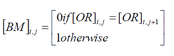 |
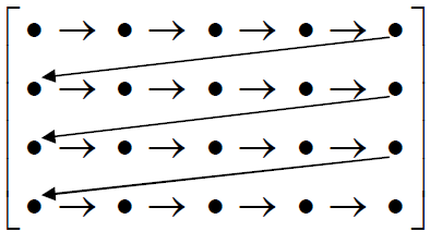 |
| Fig : 1 |
| Step 7: The original image[OR] can be reconstructed by using : |
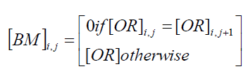 |
| The performance of the proposed algorithm is compared with other research results and predefined software such as JPEG Lossless Encoder. The criteria used for the comparison is the compression ratio achieved which is defined as follows[4]: |
| In a genetic algorithm, a population of solution called as resultant effective solution to an optimization problem is evolved to achieve a better solutions. Each candidate solution or its chromosomes or genotype which can be mutated and altered; traditionally, resulting sets or solution are represented in binary forms as strings of 0s and 1s, but other encodings can also be predicted. |
| We propose a Genetic Algorithm based text data lossless compression standard for bayer pattern.It is used to select the best patterns or pixels among the set of available patterns or pixels in the bayer pattern Image. It also achieves better compression ratio and Less Elapsed time. |
| 3.1Chromosomes: |
| The next step is to generate a second generation population of solutions from those selected through genetic operators: crossover (also called recombination), and/or mutation. For each new Chromosomes to be produced, a pair of "parent" solutions is selected for breeding from the pool selected previously. By producing a "child" solution using the above methods of crossover and mutation, a new result or effective solution is created which typically shares many of the characteristics of its "parents". New parents are selected for each new child, and the phenomena continues until a new population of solutions of appropriate size is generated. The further improvement methods that are based on the use of two parents are more, some research suggests that more than two "Solutions" generate higher quality chromosomes. Chromosomes or solutions represent solutions consisting of centers of k clusters – each cluster center is a ddimensional vector of values in the range between 0 and 255 representing intensity of gray or color component. |
| 3.2 Population initialization and fitness computation: |
| The clusters centers are initialized randomly to k ddimensional points with values in the range 0 – a 255. Fitness value is calculated for each chromosome in the population according to the rules .. |
| 3.3 Selection: |
| Selection operation tries to choose best suited chromosomes from parent population that come into mating pool and after cross-over and mutation operation create child chromosomes of child population. Most frequently genetic algorithms make use of tournament selection that selects into mating pool the best individual from predefined number of randomly chosen population chromosomes. This phenomena is repeated for each parental chromosome. |
| 3.4 Crossover: |
| The crossover operation presents probabilistic process exchanging information between two parent chromosomes during formation of two child chromosomes. Basically, one-point or two-point crossover operation can be used. |
| 3.5 Mutation: |
| Mutation operation is applied to each created child chromosome with a given probability pm. After crossover operation children chromosomes that undergo mutation operation flip the value of the chosen bit or change the value of the chosen byte to other in the range from 0 to 255. Basically mutation probability rate has a limit between 0.05 - 0.1 [4]. |
| 3.6 Termination criterion: |
| Termination criterion determines when algorithm completes execution and final results are presented to the user. Termination criterion should take into account specific requirements. Most Fundamental criterion is that algorithm terminates after predefined number of iterations. Other possible criterion for termination of the k-means algorithms depend on degree of population diversity or situation when no further cluster reassignment takes place. |
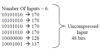
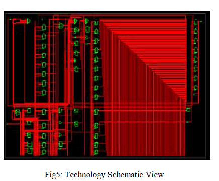
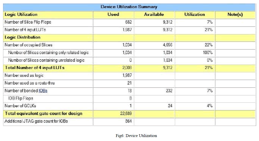
SIMULATION RESULTS |
 |
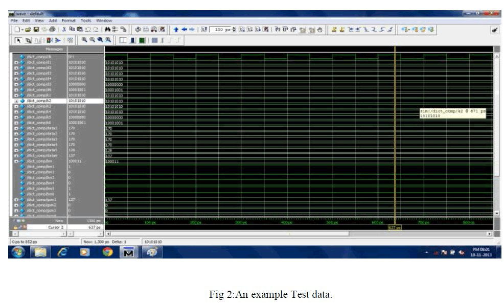 |
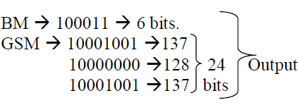 |
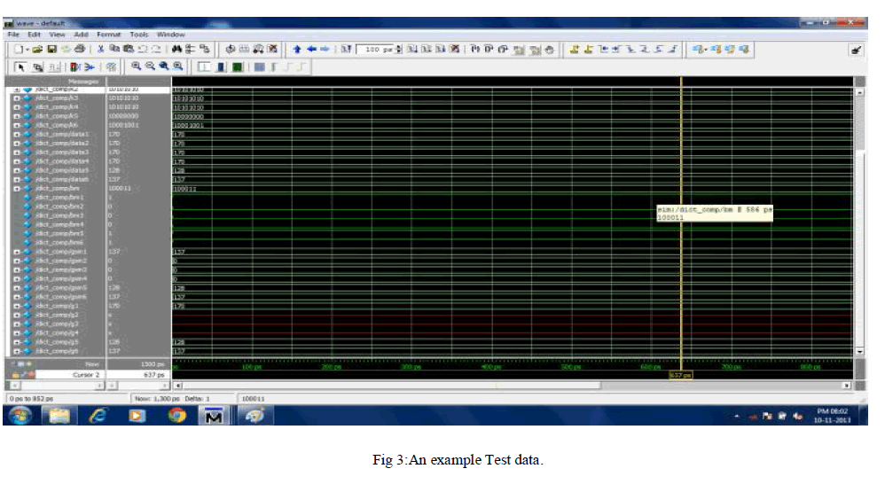 |
 |
 |
 |
CONCLUSION |
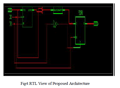
| In this project, as it has been discussed so far,the Compression of test vector using two different matrix has been achieved. The programming was done using BM and GSM and a compression was achieved at the ratio of 16%.. This algorithm helps us to arrive with desired output by the selection of best pattern.On the analysis of the results produced by proposed system it can be said that applying BM and GSM algorithm may give better results for obtaining better Compression.The simulation was done using Modelsim and device utilisation was calculated using Xilinx. |
References |
|