International Journal of Innovative Research in Science, Engineering and Technology
ISSN ONLINE(2319-8753)PRINT(2347-6710)
ISSN ONLINE(2319-8753)PRINT(2347-6710)
Prabal Deb1, Shilpi Bhattacharya2, Sujit K. Biswas3 and S. Kar. Chowdhury3
|
| Related article at Pubmed, Scholar Google |
Visit for more related articles at International Journal of Innovative Research in Science, Engineering and Technology
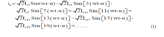
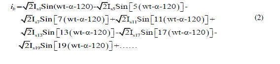
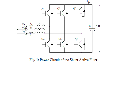
An electric supply system should invariably show ideal sinusoidal voltage and current signals at every consumer end. But in fact electric utilities hardly find such desirable conditions due to several factors. Use of wide variety of domestic and industrial equipments is one of the reasons. In order to improve the performance to cope up with technological advancements, modern semiconductor based converters are often used. These equipments are often referred to as Power Electronics loads. Solid state control of ac power using thyristors and other semiconductor switches is widely employed to feed controlled electric power to electric loads, such as adjustable speed drives, furnaces, computer power supplies, electrical transportation systems, electro domestic appliances etc. The objective of the paper is to study, simulate and design a shunt active power filter capable of compensating current harmonics generated at the supply side due to presence of such non-linear loads. The basic topology of the shunt active filter is a PWM controlled three-phase voltage source inverter bridge. A SCR or diode based rectifier is connected to the utility and the PWM controlled inverter generates specific current harmonics. These generated harmonics are injected into the source in phase opposition to the harmonics generated by the load. Thus harmonic cancellation takes place, so that these harmonics are not drawn from the source. In this paper, harmonic waveforms are generated in MATLAB software based on Fourier series of the ideal wave shapes created at the supply lines due to non-linear loads. A selection criterion for different components of the active filter has been made.
Keywords |
| Shunt Active Power Filter, Harmonic Compensation, SCR Converter, THD |
INTRODUCTION |
| Ideally, an electricity supply should invariably show a perfectly sinusoidal voltage and current signals at every consumer end. But for numerous reasons, this ideal condition of utility is hardly available in reality. To cope with technological advancements and to enhance performance, modern semiconductor based rectifiers/converters are often used which are often referred to as Power Electronics loads. Thyristors and other semiconductor switches are widely employed in Solid state control of ac power to feed electric loads, such as adjustable speed drives, furnaces, computer power supplies, electrical transportation systems, electro domestic appliances etc where controlled electric power is essential. Not only that, such controllers are also used in HVDC systems and renewable electrical power generation. Those offer viable solutions to electric power control from a few watts to many megawatts, but on the other side the nonlinear characteristics of semiconductor converters added with operational functions of most power electronics circuits generate distorted current and voltage waveforms at source. In contrast with the conventional linear loads, power electronics loads draw a non sinusoidal current from a reasonably sinusoidal voltage. Harmonic distortion expresses the deviation of the voltage and current waveforms from sinusoidal depending of its topology and load to deliver. This harmonic distortion causes unfavorable performance of electric machines, telephone interference and increases risk of faults from overvoltage conditions developed on power factor correction capacitors connected to the same utility and many others. Earlier as conservative design of power equipments dominated the industry harmonics represented less of a problem where as in the recent past increasing use of nonlinear loads in industry is keeping harmonic distortion in distribution networks on the rise. The presence of power electronics related distorting elements in almost all major industrial loads is regarded by the power distribution organizations as the major cause of an alarming amount of harmonic distortion in electric power systems. The non sinusoidal current generated due to non-linear loads causes a corresponding non sinusoidal voltage drop on the line impedance, producing a distorted voltage. These loads are commonly referred to as “power system polluter” or “distorting sources “in relevant literatures. This situation has thrown a serious challenge to industry and utility engineers to pinpoint and to correct excessive harmonic waveform distortion levels on the waveforms because its steady increase happens to take place right at the time when the use of sensitive electronic equipment is on the rise. Thus it is quite evident that harmonic studies from the planning to the design stages of power utility and industrial installations will prove to be an effective way to keep the power networks and also the equipments under acceptable operating conditions and to anticipate potential problems with the installation or addition of nonlinear loads. Active Power Filter is an well defined solution to this utility distortion. The idea of active filter was introduced by Gyugyi et al [1] in 1976 .The term active filter is a generic one and is functional to a multitude of power electronic systems comprising power switching devices and other energy storage circuit elements, such as inductors and capacitors. Active power filters are basically used to recompense for the harmonics introduced into the power lines due to loads with non-linear characteristics. These are designed to implement the well established concept of injecting[1,6,7] the equal and opposite distortion current waveform to the power supply bus-bar system in order to enhance the power quality of the bus bar. The primary idea is to make the power supply current near sinusoidal, the measure of which is the total harmonic distortion. The lower the THD, the better is the shape of the synthesized sinusoidal current at the source. Since the basic configuration of the active filter involves a power switching circuit, a control strategy is a prerequisite for driving the power switch accordingly to generate the desired harmonic wave shape. Hence, keeping this in mind, two such methods can be used here to command the power switching circuit. One is the hysteresis control technique, where the error function is centered in a predefined hysteresis band. When the error tries to cross the upper or lower hysteresis limit, the controller makes an appropriate switching decision [3] to restrict the error within the prescribed band. The other method is the one in which the error is compared with a fixed high frequency triangular carrier signal. The intersection of these two waveforms determines the switching instants of the switching device. Though both the approaches have been widely used but the former suffers from a serious demerit of operating the switch at an unknown variable high frequency. In this work a fixed frequency control method has been followed. Basically, active power filters have been realized using two types of converters voltage source inverters (VSI) and current source inverter (CSI). Current fed pulse-width modulated inverter bridge structure is considered reliable but has higher losses and requires an inductor at the dc side. The other active power filter based on VSI has a self supporting dc voltage bus with a large dc capacitor. This converter topology [7] is well accepted as compared to the CSI version since it is lighter, cheaper and expandable to multilevel and multistep versions, to boost the operation with lower switching frequency. Also in high power applications capacitor is more suited than an inductor. Consequently, the active power filter considered here for simulation purpose is a three-leg current controlled voltage source converter. This forms the major power circuit shown in Fig.1, which is designed here using IGBT’s owing to their capability to operate at a relatively high power at high switching frequency. This paper presents the concept of creating a composite current waveform [2, 4] consisting of all the harmonic components for a definite load to compensate for the input current harmonics drawn by a SCR converter. |
 |
 |
III. CURRENT CONTROLLER |
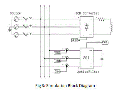
| A shunt active power filters as shown in Fig. 3 have been recognized as a solution to reduce the harmonic content in the current waveform generated at the source due to non-linear loads (diode, thyristor rectifiers etc.) connected. The basic principle of shunt active filter is the creation and injection of the harmonic currents in anti-phase into the supply system. |
 |
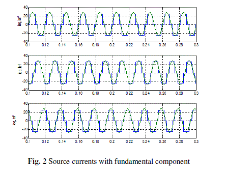
| The maximum harmonic order that an active power filter is able to compensate defines the filter bandwidth. The current becomes near sinusoidal after compensation. There are many pre-established current control pulse-width modulation techniques [5, 7] having their own merits and demerits. The controller here is a PWM current based modulation technique. The currents to be fed to the controller are the generated reference current and the measured actual current. So, firstly the reference current waveform is to be created. In this study the reference currents are generated following these steps:- (i) Three quasi-square waveform as shown in Fig.2 is established by a MATLAB based program for three phases. (ii) The fundamental sinusoidal waveforms are also created based on (1-3) and incorporated in the MATLAB program. (iii) Now the created fundamental is subtracted from the quasi-square waveform to obtain an all harmonic composite waveform devoid of the fundamental component of current. The waveform obtained now is the reference current waveform. The line currents are sensed and fed to the current controller. The error between the reference current and the measured current is compared with a triangular signal of high carrier frequency to produce pulse-width modulated signals for switching the six IGBT’s, in a three-phase full-bridge VSI. A digital simulation of the entire active power filter set-up is accomplished in MATLAB/Simulink. The controller is developed in this work by standard Simulink blocks as shown in Fig. 4 and embedded as subsystems in the main power circuit. The major components of the active filter i.e. line inductor and dc bus capacitor although calculated from some design equations given later but exact values needs a trade-off from calculated ones for proper compensation. Thus to obtain the best values of the line inductor and dc capacitor, rigorous simulations were performed to ascertain the lowest possible percentage THD line currents after filtering |
 |
IV. SIMULATION RESULTS AND DISCUSSION |
| The simulation results are shown in Fig. 5 through Fig.8. The generated reference currents for the three phases are obtained from programming in MATLAB Simulink are shown in Fig.5. The capability of the controller in delivering the harmonic currents and as a result reducing the harmonic content in the source current waveforms is depicted in Fig. 6. Initially the diode rectifier is connected to the utility without the shunt active filter connected, and it can be seen how the source currents are of square wave-shape. At 0.2 sec the active power filter is started and the source currents are seen to change to near sinusoidal waveform in Fig. 6(a). In Fig. 6(b) the load currents are seen to remain square waveforms although the source currents are near sinusoidal. Fig. 6(c) shows the injected harmonic current and also the sinusoidal current wave-shape with minimized harmonic content. Fig. 7 and Fig.8 shows the controller performance for a SCR converter connected as non-linear loads. A triggering angle of α = 30o is considered in Fig.7 and the results for α = 60o are shown in Fig.8. The sudden change of the somewhat quasi-square nature of current into a near sinusoidal one after switching on the active filter can be easily observed in both the set of waveforms of Fig7 and Fig. 8. |
V. COMPONENT SELECTION FOR SHUNT ACTIVE FILTER |
| The power circuit of the inverter implemented in this work is a three-leg current controlled voltage source inverter topology with a dc bus capacitor and a set of three input reactors. The current controller [5] forces the semiconductor switches of the inverter to deliver the harmonic currents into the three-phase AC source. The inverter operates as a controlled current source. The dc side of the inverter as mentioned is an energy element rather than a power supply, as the shunt active filter can be controlled to supply the losses in the inverter from the ac network side. Power circuit design of the shunt active filter involves the selection of the value of the filter capacitor, line reactor, and the choice of controllable power devices and the nominal value of the capacitor voltage. IGBT (Insulated Gate Bipolar Transistor) is chosen here as the active power switch owing to their behavior to support unipolar voltage and |
 |
| should be high enough to eliminate harmonics upto a certain frequency. Theoretically, the switching frequency of the IGBT’s should be twice of the maximum harmonic frequency to be eliminated. Some basic criteria are followed while designing the reactor and the dc capacitor values. The peak amplitude of the injected current of the high frequency components is to be restricted to an acceptable value of the rated value of the load current. The instantaneous di/dt generated by the shunt active filter should be greater than the di/dt of the harmonic component of the load so that proper harmonic neutralization is possible. The tracking of the filter inductor current with the generated reference current improves when the filter inductor value is made smaller. The mathematical design equations are as given below as detailed in [6]. |
 |
 |
| The perfect value of dc bus capacitor is obtained by simulation. Here the study has been carried out with Lf = 0.8 mH and C= 2500μF. It is also observed that a filter inductor as low as 0.5mH also suffices but the current ripple increases in that case, also a higher value of inductor 2mH also gives suitable tracking of the desired current at a high switching frequency of 30KHz. Beyond this value the current is never able to follow the template and thus results in a high THD and complete failure of the active filter. The active filter circuit is also tested with various capacitors ranging from 1500μF to around 4000μF and it is seen to operate successfully. |
VI. CONCLUSION |
| This paper proposes a simple technique for reducing current harmonics introduced into the supply system due to the presence of power electronic converters. The power electronic converters considered in this work are diode rectifiers and SCR based three-phase converters. The efficacy of the technique is proved by the percentage THD which is greatly reduced to a considerably low value. The MATLAB simulation here gives a justification of the operation of the active power filters with a non-linear load. The case studies for diode rectifier show that the currents are near sinusoidal. In the same way for a SCR converter operating at two different firing angles, the harmonic compensation is shown to be quite effective. A basic design of an active power filter is analyzed and the fundamental structure of the entire set-up is discussed. |
References |
|