ISSN ONLINE(2319-8753)PRINT(2347-6710)
ISSN ONLINE(2319-8753)PRINT(2347-6710)
Swagat Prasad Das1, Sangram Keshari Samal2, Radharaman Dalai3, Manas Ranjan Padhi4
|
| Related article at Pubmed, Scholar Google |
Visit for more related articles at International Journal of Innovative Research in Science, Engineering and Technology
In this research work the main aim is to reduce the induced drag by using single slotted raked wingtip. Here two wingtip geometries such as a sweptback & tapered wingtip and a slotted raked wingtip are taken for the research work. The tip vortex characteristics of the two different wing geometries at various angles of attacks are shown for different Reynolds numbers such as (1.82 x 10⁵, 3.12 x 10⁵ and 4.16 x 10⁵). These Reynolds numbers are found out by changing the value of free stream velocity only keeping other values constant. The prediction for the numerical result of tangential velocity, lift coefficient and drag coefficient of sweptback and tapered NACA 0015 wing are compared with the experimental results. The numerical results that are obtained by using CFD code show a good agreement with the experimental results. It is observed that, the effect of Reynolds numbers on non-dimensional aerodynamic parameters are seen at higher angles of attack, i.e. above 8° for lift coefficient and above 6o for drag coefficient. It is found that the maximum coefficient of lift (CL max), stalling angle and non-dimensional aerodynamic parameters are increased whereas the drag coefficient is decreased with increase in Reynolds numbers. It is observed that the induced drag is reduced for a single slotted raked wingtip with increase in aerodynamic efficiency as compared to sweptback & tapered wingtip.
Keywords |
| Wingtip, Reynolds number, Tip-vortex, Raked, Slotted, Circulation |
INTRODUCTION |
| In aerodynamics, induced drag or lift dependent drag is a drag force that occurs whenever a moving object redirects the airflow coming at it. This drag force occurs in airplanes due to wings or a lifting body redirecting air to cause lift. With other parameters remaining the same, induced drag increases as the angle of attack increases. The viscous effects that are governed by the Reynolds numbers have a major influence on the airfoil lift, drag, and other aerodynamic characteristics. So it is essential to analyse the effects of the Reynolds numbers on reduction of wing tip vortex and hence reduction of induced drag. The Reynolds number is a dimensionless number that facilitates a full scale aerodynamic configuration to compare with a test model, giving incite to the forces as well as the aerodynamic characteristics as expected. |
| Different simulations were made for the three different Reynolds numbers such as 1.82 x 10⁵, 3.12 x 10⁵ and 4.16 x 10⁵. The basic objective of the recent work is to find out the effects of the Reynolds numbers on wing tip vortex and reduction of induced drag using Single Slotted Raked Wingtip. In a finite wing, there is an opportunity for the pressures acting on the upper and lower surfaces to interact near the wing tip [1]. The shorter the distance between the wing tip, the larger the downwash velocity and the induced drag [2]. The trailing vortex system also generates an up wash in the regions beyond the wing span and a downwash inside the wing span. This downwash produced by the trailing vortex system adds to the downwash produced by the bound vortex system [3]. |
| Aerodynamic efficiency can be improved by increasing the maximum lift-to-drag ratio at the cruise flight condition, because induced drag is typically 30 percent or more of the total drag on a subsonic transport in cruising flight [4]. A 10% drag reduction on a large military transport aircraft is estimated to save up to 13 million gallons of fuel over its lifetime [5]. The worlds total jet fleet is estimated to be approx. 17 thousand aircrafts [6]. Such reduction in drag could result in fuel savings up to 1x10¹⁰ U.S. dollars ($). This drag is even more significant at low speeds, during takeoff conditions, where it accounts for 80-90% of the aircraft drag [7]. Besides the advantages of lowering operating costs, reducing wingtip shed vorticity, and therefore induced drag, may also reduce global warming because of the lower fuel consumption. The world’s commercial jet aircrafts generate more than 600 million tons of carbon dioxide per annum [8]. The methods adopted for reducing tip vortices are winglets, wingtip sails, and Raked wing tips. Most of the development work for the winglet was initiated by Whitcomb at NASA [9], [10]. Adding winglets to a wing can reduce and diffuse the vortex structure which originates at the tips [5, 12, and 13]. Also wing tip vortex can be reduced by using active means (i.e. suction at wing tip) rather than using passive means (i.e. shaping the wingtip )[14, 15]. |
| The need of faster and more accurate methods for the calculations of flow fields around the wingtip configurations led to the rapid evolution of CFD. This paper presents the validation of CFD code against experimental data given by McGill University and investigates the 3-D flow structure of two different configurations viz. sweptback & tapered wingtip and wing with slotted raked wingtip, at Re=1.81 x 10⁵. Special attention was given to the effects of Reynolds numbers on aerodynamic characteristics of sweptback & tapered wingtip and single slotted raked wingtip. |
II. PROCEDURE |
a. Overview |
| This paper presents a comparison between wingtip vortex flow field done by CFD simulations and experimental measurements done at McGill University by P. Gerontakos and T. Lee, [11] as a validation of the present numerical CFD simulations. Also several parameters were computed for the two different configurations at different Reynolds numbers and presented in graphical format. The Reynolds number is dependent upon the density of the fluid, the average velocity of the airfoil relative to the fluid, the characteristic length of the airfoil, as well as the dynamic viscosity of the fluid. Reynolds numbers were changed by changing the free stream velocity and keeping other parameters constant. We can also be able to predict all aspects of the tip-vortex using modern CFD code with commendable accuracy for an unswept and sweptback wing [16, 17]. |
| The present simulations were run in ANSYS 13.0, which models fluid flow and heat transfer problems in complex geometries. This commercial CFD software solves the general transport equations using the finite volume method. Steady-state, transient, incompressible, compressible, in-viscid, viscid, laminar, and turbulent flows can be solved by using Fluent. The simulations were also run for three different Reynolds numbers (1.82 x 10⁵, 3.12 x 10⁵ and 4.16 x 10⁵) by changing only the free stream velocity. Only the free stream velocities were changed to obtain the different Reynolds numbers. The free stream velocities were set to 35 m/s, 60 m/s. and 80 m/s to achieve the corresponding Reynolds numbers. |
| The present simulations were run in ANSYS 13.0, which models fluid flow and heat transfer problems in complex geometries. This commercial CFD software solves the general transport equations using the finite volume method. Steady-state, transient, incompressible, compressible, in-viscid, viscid, laminar, and turbulent flows can be solved by using Fluent. The simulations were also run for three different Reynolds numbers (1.82 x 10⁵, 3.12 x 10⁵ and 4.16 x 10⁵) by changing only the free stream velocity. Only the free stream velocities were changed to obtain the different Reynolds numbers. The free stream velocities were set to 35 m/s, 60 m/s. and 80 m/s to achieve the corresponding Reynolds numbers. |
b. Complete Geometry Case |
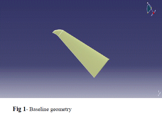
| The near-field flow structures of two different configurations (such as, sweptback & tapered wingtip and wing with slotted raked wingtip) were investigated using Computational Fluid Dynamics (CFD). The baseline geometry(tapered sweptback wing configuration) was a half-wing model (Fig. 1) used by P. Gerontakos and T. Lee [11] at McGill University in a low speed wind tunnel. The model is an untwisted sweptback, tapered wing with an aspect ratio of 3.654, a taper ratio of 0.375, a semi-span of 51 cm, and a wing area of 713 cm2. The root chord is 20.3 cm and the tip chord is 7.6 cm. This test model was used for three different free stream velocities for 35 m/s, 60 m/s. and 80 m/s. The locations of the downstream vortex-flow measurement planes (denoted by the dashed lines, x/cr=2) are shown in Fig.1. The sweep angle at 0.25-chord location was set at 240. The square tipped wing had a NACA 0015 section throughout the span at 8° angle of attack. |
 |
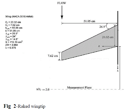 |
| The second configuration (single slotted raked wingtip) was created from base line configuration. The tapered sweptback wing (baseline geometry) was modified to raked wingtip (Fig. 2) by changing the wing tip geometry only. |
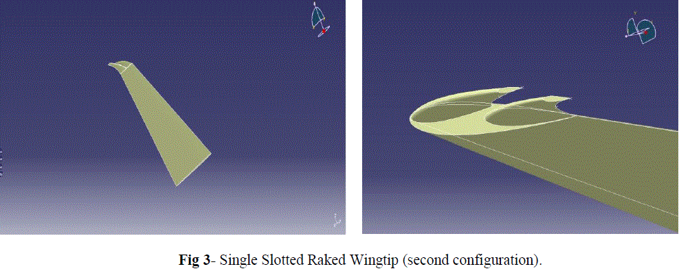 |
| The wing tip was modelled similar to raked wingtip configuration of Boeing 787. Then the raked wingtip geometry was modified keeping a slot like on a bird’s feather to get a raked part as shown in Fig. 3 to create the single slotted raked wingtip. |
III. RESULTS AND DISCUSSION |
| The main objective of this work was to investigate the tip vortex characteristics for different Reynolds numbers, for which two different wingtip configurations, such as sweptback &tapered wingtip and single slotted raked wingtip, were taken at various angles of attack. This research work includes three sections. The first section tells about the validation of the CFD code with experimental data and the other two sections elucidate the effects of Reynolds number on tip vortex characteristics of sweptback & tapered wingtip and single slotted raked wingtip configuration. |
a) Validation of the CFD code: |
| At free stream velocity of 35 m/s, the non-dimensional tangential velocity distribution ((vθ/u∞) was calculated about the vortex centre at 8° angle of attack. This computed value was compared with the experimental result done at McGill University by P. Gerontakos and T. Lee,[11] . |
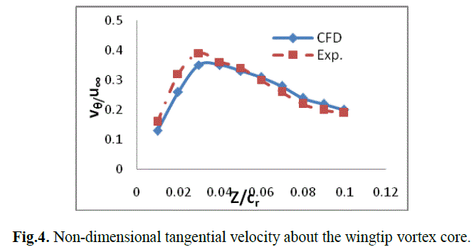 |
| Fig. 4 shows a comparison between numerical simulations done in Fluent and the experimental result of vθ/u∞. The simulation shows a good agreement with the experimental data. |
b. Investigation of sweptback tapered wing |
| The circulation can be calculated either by taking line integral of velocity around a closed curve or by the surface integral over vorticity [18, 19]. The circulation value can be obtained from the surface integral as follows... |
 |
| Both the line and surface integral methods were used to calculate the circulation. As no significant difference was found between these two calculation methods so only line integral method was used to find out the circulation. Different flow parameters were computed for the three different Reynolds numbers at various angles of attack and represented graphically in Figure 5. |
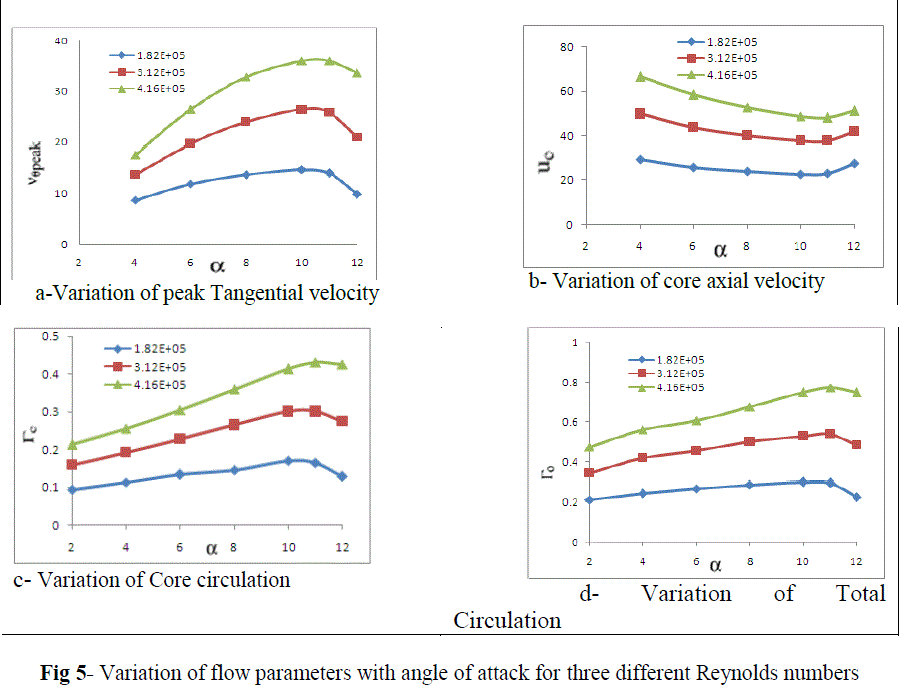 |
| It is noticed that with increase in angles of attack, the values of vθpeak, Γc and Γ0 were increased and uc was decreased. It is found that, while increasing the angles of attack, the flow parameters (vθpeak, Γc and Γ0) show a continuous increasing trend whereas uc shows a decreasing trend for different Reynolds numbers. Dimensionless flow parameters were computed for the three different Reynolds numbers at different angles of attack and presented in graphical format in Figure 6. |
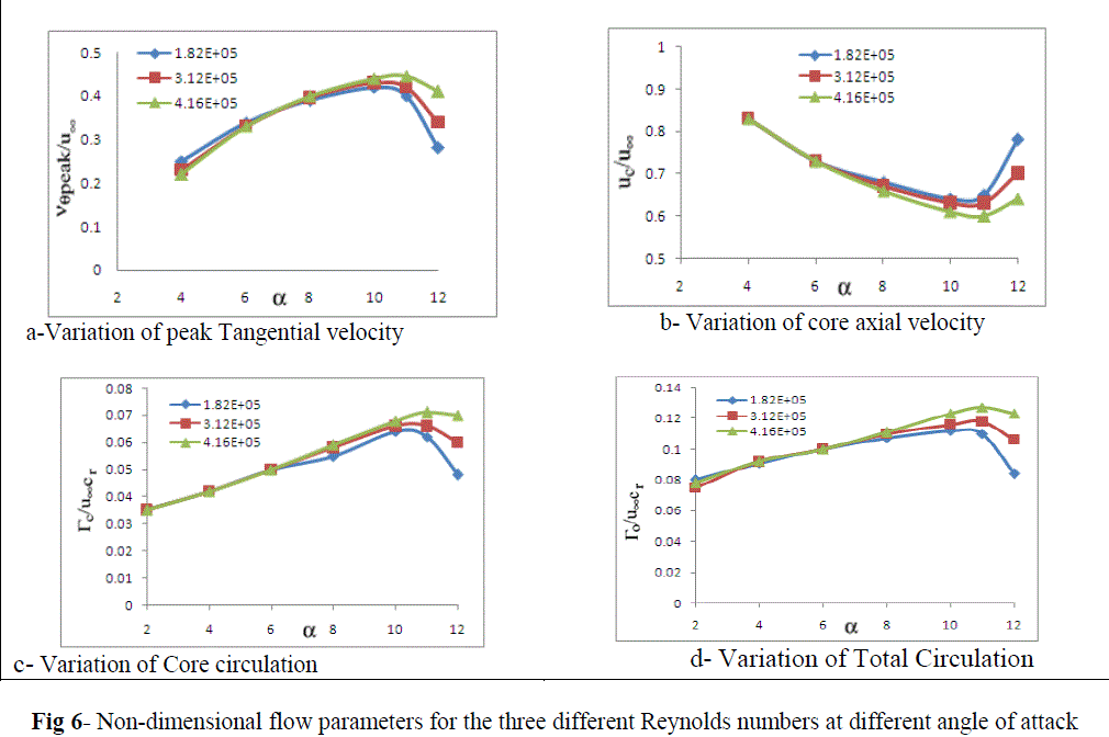 |
| No significant difference in vθpeak, Γc, Γo and uc was found at lower angles of attack but the effect of Reynolds numbers was noticed at higher angles of attack. The flow parameters increase with increase in Reynolds numbers at higher angles of attack (i.e. above 8o). |
 |
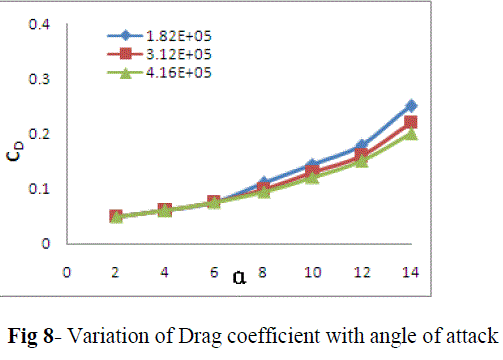 |
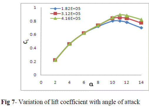
| Between angles of attack of 2o to 14o, the values of lift and drag coefficients were calculated. Figure 7 and 8 shows the variation of lift and drag coefficient respectively with different angles of attack for the three different Reynolds numbers. Till 8o angle of attack no significant effect of Reynolds number was noticed on CL. But after 8o angle of attack, noticeable changes in the (CL~ α) curve were found for different Reynolds numbers. It was observed that, the maximum CL and stalling angle increases with increase in Reynolds numbers. But in case of drag coefficient the effect of Reynolds numbers was noticed earlier than lift coefficient (i.e. above 6o angle of attack). The Drag and lift coefficients were decreased and increased respectively with increase in Reynolds numbers at higher angles of attack |
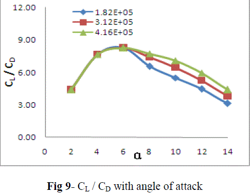 |
| Aerodynamic efficiency (CL / CD) was also calculated and represented graphically format. Figure 9 shows the variation of aerodynamic efficiency with different angles of attack between 2o to 14o for the three different Reynolds numbers. The aerodynamic efficiency was not affected by any variation of Reynolds numbers at lower angles of attack but it increases with Reynolds numbers at higher angles of attack (i.e. above 6 degree). |
c. Investigation of single slotted raked wingtip configuration |
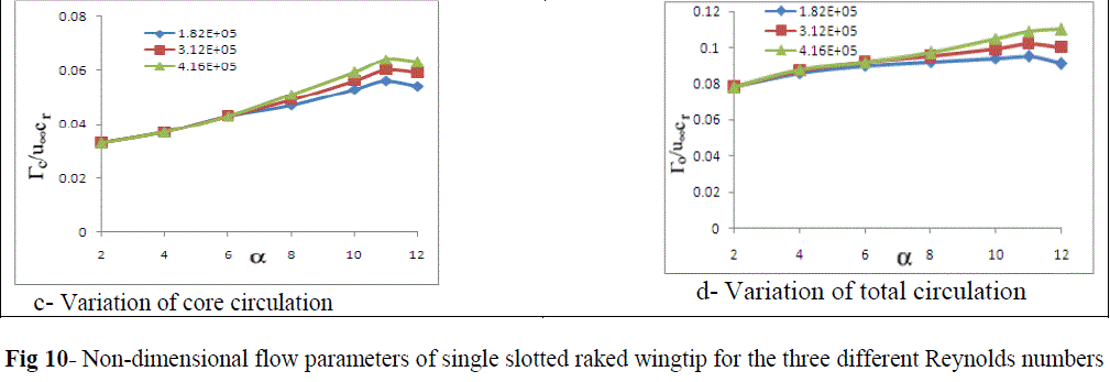
| The dimensionless flow parameters were computed for the three different Reynolds numbers and presented graphically in Figure 10. The detailed comparison between sweptback & tapered wingtip and wing with slotted raked wingtip for three different Reynolds numbers are given in next section. |
 |
Comparison between two configurations (sweptback & tapered wingtip and wing with slotted raked wingtip) |
| The graphs shown in Figures 11, 12, 13 entails about the comparison of lift coefficient, drag coefficient and aerodynamic efficiency respectively, between sweptback & tapered wingtip and single slotted raked wingtip for three different Reynolds numbers. |
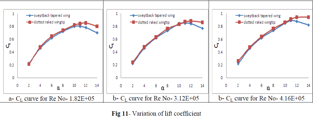 |
| The graphs shown in Figures 10 shows comparison of lift coefficient, between sweptback & tapered wingtip and single slotted raked wingtip for three different Reynolds numbers. . Till 10o angle of attack no significant difference was found for the CL- α curve but above that noticeable changes were detected. The values of CL and αStall are increased for single slotted raked wingtip as compared to sweptback tapered wingtip (figure 11) |
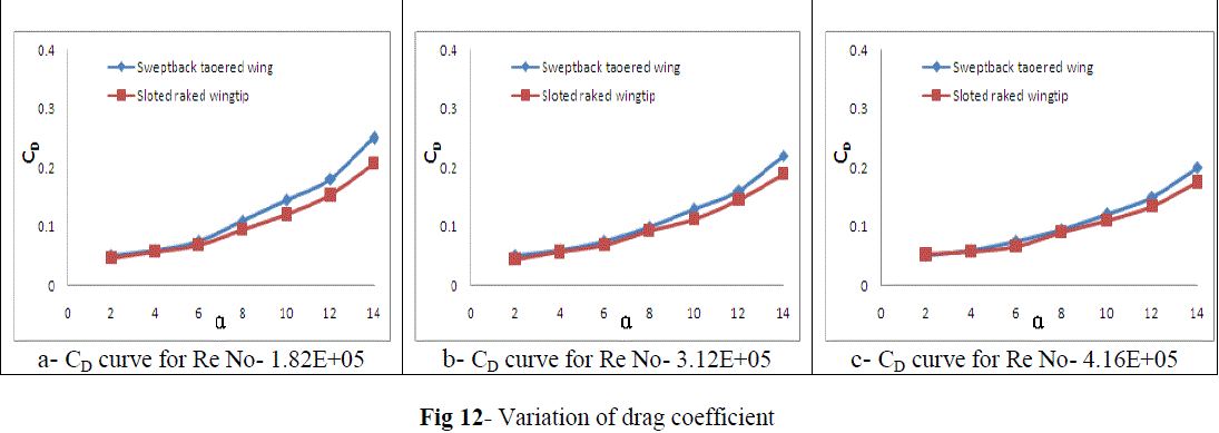 |
| Figure 12 shows different values of drag coefficients at various angles of attack for the three different Reynolds numbers. At lower angle of attack (i.e. less than 5o) no noticeable difference was found in CD but the effect was noticed on the slotted raked wingtip configuration above 5o angle of attack. |
 |
| Figure 13 gives the comparison of different aerodynamic efficiencies (CL / CD) and it was found to be more for single slotted raked wingtip than sweptback tapered wingtip. |
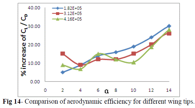 |
| Fig 14 shows the increase of aerodynamic efficiencies for single slotted raked wingtip as compared to sweptback tapered wingtip. |
IV. CONCLUSION |
| In this research work the influence of Reynolds numbers for two different wingtip configurations (such as, sweptback tapered wingtip and the single slotted raked wingtip) were investigated at different angles of attack by using the numerical simulations in FLUENT. The flow structure of a tip vortex behind a sweptback and tapered NACA 0015 wing with an AR of 3.654 was investigated for three different Reynolds numbers (i.e. 1.81x10⁵ , 3.12x10⁵ and 4.16x10⁵) at different angles of attack for the two different configurations (sweptback-tapered wingtip and single slotted raked wingtip). Numerical simulations done in the current study has shown very good agreement with the experimental measurements done by P. Gerontakos and T. Lee at McGill University in predicting the formation of wing tip vortices for a sweptback tapered wing. |
| Initially, the peak tangential velocity, core circulation and total circulation were found to be increased with increase in angles of attack up to 100 and then tend to decrease for all the three Reynolds numbers. The angle of attack was higher for single slotted raked wingtip than that for sweptback tapered wingtip. But the value of uc was found to be decreased initially up to 100 and then increased for all the three Reynolds numbers. No significant difference was noticed in the dimensionless parameters (viz. vθpeak, Γc, Γo and uc) at lower angles of attack but at higher angles of attack the effect of Reynolds numbers was observed (figure 5). For all the three different Reynolds numbers the values of CL, CD and CL/CD for both the configurations were computed. The effects of Reynolds numbers were not observed for CL and CD up to certain angles of attack, but the effects were noticed above 8o angle of attack for CL- α curve and above 6o angle of attack for CD – α curve. With increase in Reynolds numbers, the value of CL max and stalling angle were found to be increased for both the configurations but the drag coefficient was found to be decreased. The effects of Reynolds numbers on aerodynamic efficiency were observed above 6o angle of attack. With the increase in angle of attack, the percentages of aerodynamic efficiency were increased for all the three Reynolds numbers. It is also found that, aerodynamic efficiency was higher for single slotted raked wingtip than sweptback tapered wingtip for all the three Reynolds numbers. |
| Based on the present study, it is concluded that, the effects of Reynolds numbers on the aerodynamic characteristics are found at higher angles of attack but not at lower angles of attack. The increase in aerodynamic efficiency is more for single slotted raked wingtip as compared to sweptback tapered wingtip, which ultimately leads to reduction of induced drag. For further investigations, it would be very helpful to investigate its impact on the very low Reynolds numbers and compressible flow. |
References |
|