ISSN ONLINE(2319-8753)PRINT(2347-6710)
ISSN ONLINE(2319-8753)PRINT(2347-6710)
Prabhakar.A1, Dr. Mohamed Haneef2, Shabbir Ahmed R.M3
|
| Related article at Pubmed, Scholar Google |
Visit for more related articles at International Journal of Innovative Research in Science, Engineering and Technology
Forming is the most important manufacturing process. Forming is the process of converting the geometry to the required shape. Forging, extrusion, rolling and bending are some of the important forming process. The forming process includes larger deformation of the structure either with temperature or without temperature application. But in the every mechanical process certain defects exists due to the inherent resistance property of the material for forming it to the required shape. One type of defect is spring and is very important phenomenon which makes the object nonsuitable in case of rigid requirements. Spring back is mainly due to Bauchigner effect which allows the material to follow different paths during loading and unloading cycles. All forming process will take places in the plastic region. So to analyse or to estimate spring back, nonlinear material properties which will accommodate stress strain relations in the nonlinear regions are required In the present work, spring back phenomenon with steel material is analysed using Finite element software Ansys. Two parameters are considered for finding the spring back effect. Initially the sheet metal thickness effect on spring back is analysed. The geometry is built and meshed with 4 noded quad elements which allow plastic properties. Eulerian contact definitions are created between the punch, die and sheet metal with large deformation effects. The displacement loading is applied through the punch. Targe169 and contac172 elements are used for forming process. The results for vonmises stress, residual stress, plastic strain, spring back deformations are captured and tabulated. Similarly the analysis is continued with depth of forming process and its effect on spring back. The results shows with the thickness spring back values are coming down but with the depth of deformation spring back values are increasing. So finite element simulation helps in finding the inaccuracy levels if the member material properties are given which helps in setting the tolerances for the geometry either for assembly or surface finishing operations. All the values like vonmises stress, residual stress, contact pressure, plastic strain and spring back are increasing with depth of the forming process.
Keywords |
| Forming, spring back effect, Bauchigner effect, vonmises stress, residual stress, Ansys, |
INTRODUCTION |
| Bending of sheet metal is one of the widely used in industrial process, especially in automobile and aircraft industries, sheet metal bending is one of the most widely applied sheet metal forming operation. Bending is such a shaping process used commonly in various sheet metal industrial products. The sheet parts in these products and in the others are shaped using bending dies. According to the shape of the product, the bending is divided into the following. |
| Air bending. |
| U-bending |
| V-bending. |
| Roll bending. |
| Edge bending. |
| The accuracy and success of the bending process depends upon the operating parameters as well as, material properties, clearance, radius of the die and punch, friction condition etc. In past, sheet metal bending processes are dependent on the designer's experience and involve trials and errors to obtain the desired result. Many analytical models are proposed to study spring back in bending by using simple beam or plate bending and these models use a simplified assumption. |
METHODS AND METHODOLOGY |
| 1. Finite Element Method |
| The finite element method is a numerical method, which can be implemented to solve many problems. An assembly process, duly considering the loading and constraints, results in a set of equations, solution of these equations gives us the approximate behavior of the continuum. The analysis which uses FEM is known as FEA. A general purpose FEA program consists of three modules; a pre-processor, a solver, and a post processor. Commercial FEA programs can handle very large number of nodes and nodal degrees of freedom provided a powerful hardware is made available. User’s manual, theoretical manual, and verification problems manual, document a commercial FEA program. |
| 2. ANSYS Analysis |
| A typical ANSYS analysis has three distinct steps: |
| 2.1 Building a Model |
| Building a finite element model requires more time than any other part of the analysis. First, the user specifies a job name and analysis title. Then using the pre-processor, the element types are defined, element real constants, material properties, and the model geometry. |
| 2.2 Loading |
| The main goal of a finite element analysis is to examine how a structure or component responds to certain loading conditions. Specifying the proper loading conditions is, therefore, a key step in the analysis. Loads can be applied on the model in a variety of ways in the ANSYS program. The word Loads in ANSYS terminology includes boundary conditions and externally or internally applied forcing functions. |
| 2.3 Review the results. |
| Post Processing |
| The postprocessors in the ANSYS program can help the user to obtaining the solution and others. Post processing means reviewing the results of an analysis. It is probably the most important step in the analysis. |
| 3. CONTACT STRESS ANALYSIS |
| Contact problems are highly nonlinear and require significant computer resources to solve. Contact problems present two significant difficulties. First, the exact area of contact will not be known until the problem is executed. Depending on the loads, materials, boundary conditions, and other factors, surfaces can come into and go out of contact with each other in a largely unpredictable and abrupt manner. Second, most contact problems need to account for friction. |
| 4. PERFORMING a Surface-to-Surface Contact Analysis |
| We can use the surface-to-surface contact elements to model either rigid-flexible or flexible-flexible contact between surfaces. The Contact Manager, accessible through the Main Menu>Preprocessor>Modeling> Create> Contact Pair menu item, provides an easy-to-use interface to help to construct and manage contact definitions. |
METHODOLOGY |
| Geometrical Modeling to the required specifications |
| Quad meshing using Plane strain approach |
| Map meshing using regular geometry divisions by ansys work plane options |
| Application of boundary conditions |
| Creation of contact pairs and elimination of die and punch area to minimize the number of elements |
| Nonlinear analysis to find contact behavior and spring back in the system |
| Querying the displacement after the load remove for find the spring back value and results presentation. |
RESULTS AND DISCUSSION |
| 1. Material Specifications: |
| Material: steel, Young’s modulus=200Gpa, Density =7800kg/m3, Yield stress=250Mpa, Plastic Modulus=3000Mpa. |
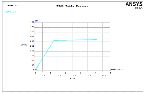 |
| The figure1 shows bilinear representation of the problem. The material is considered as elasto-plastic with strain hardening behavior. Up-to yield point tangent modulus will be defined and later plastic or tangent modulus will be defined for the problem. Generally plastic modulus value is small compared to the Young’s modulus value specified. The material will follow linear relation up to yield point and later follows tangent modulus for strain calculation. This is region is the source of residual stresses in the structure. Also this region influences the spring back phenomenon. |
| 2. Model Specifications: |
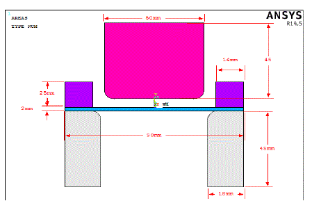 |
| The figure2 shows geometrical parameters of the spring back system. The dimensional details are given in the problem. The primary objective is to analyse the effect of thickness on spring back of the problem. Ansys mixed approach is used to built the geometry. Different colours are used to represent the problem. Thickness of the sheet metal is considered as 2 mm. The mixed up approach considers point, line and area approach for complicated object (Punch and die) and direct rectangle creation for the sheet metal. |
| 3. Mesh Specifications: |
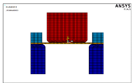 |
| The members are map mesh with the appropriate material properties. Steel properties are given for sheet metal and rigid material properties are given for die and punch members. Since the sheet metal is the point of interest, the body is meshed with deformable material properties. Plane182 element with plane strain option is used for meshing. Plane182 element has the properties of large deformation effects which is the essential requirement of the forming materials. A finer mesh is considered at the corner regions for better convergence. 1580 elements and 1693 nodes are used for meshing half symmetric geometry. |
| 4. Analysis Results (Thickness 2mm): |
| Analysis has been carried out after giving displacement to the punch elements. Here the area mesh of both punch and die are cleared to increase the speed of computation. This is possible after the contact pairs are created. So the punch target elements are given the required displacement load for bending process. The die target nodes are fixed in the position. Incremental procedure based on Newton Raphson method is applied to solve the problem in the nonlinear material and geometrical domain. The result for 2mm thickness sheet metal is as follows. |
| 4.1: Displacement Results for 2mm plate thickness: |
| The iteration process gives the required number of steps for proper convergence of the problem. In each step the punch will move smaller distance and the effect of this on sheet metal and die are shown. This iteration process helps the user to understand the process of bending process. Initially displacement pictures are captured. Later Stress pictures are captured. The iteration summary shows the development of the parameter of interest in the pictorial representation. |
| 4.2: Vonmises stress development for plate thickness 2mm: |
| The stress developing after the punch touches the sheet metal. The stress value is crossing the yield point after certain steps and later the stress increase is sloping down due to plastic condition of yielding. The stress above yield stress shows yielding of the member which is the cause of residual stress formation in the structure. |
| 4.3: Contact Pressure Development: |
| The simulation helps in finding the load requirements for given punch movement. The maximum pressure developed is at the fillet and corner regions and in the final loading stage and reduces after load is removed. The simulation helps in the geometrical modeling of correct die. The contact pressure shows the regions of stress generation due to the shape of the die and punch. |
| 4.4: Spring Back (2mm thick): |
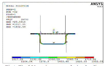 |
| The figure 4 shows final vonmises stress in the structure. Maximum stress is around 1802.59Mpa at the bottom bent corner of the sheet metal. This can be attributedto higher deformation at the bent region. The strain is directly proportional to stress. Here strain is maximum due to plastic yielding of the sheet metal. Minimum stresses are developed at the end portions of sheet metal which are not displaced from the original configuration. The status bar at the bottom shows the stress variation in the geometry along the sheet metal. Vonmises stress is considered for plastic condition as the vonmises theory of failure is the most used theory in the failure of ductile materials. Vonmises stress is the stress corresponding to the stored energy and also it is called as equivalent stress. Generally the structures are called yielded after it is crossing the yielding stress of the material. |
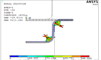 |
| The figure5 shows final contact pressure in the problem. Maximum contact pressure is around 614.686Mpa as shown in figure. Higher contact pressure generally shows higher load requirement along with improper die and punch shapes. Always less contact pressure is desirable for better results. Finite element simulation helps in predicting the contact pressure at every stage by which die and punch shapes can be varied for better design. Maximum contact pressure is taking place at the extreme tip of the sheet metal or central portion of the sheet metal. Contact pressure can be estimated by standard herzian formulation for simple contact problems. But this is difficult with metal forming process where continuous change of interface pressures. So finite element analysis is the best way of predicting the contact pressure in the process. |
| 4.5: Spring Back (Thickness 2mm) – Unloading Condition: |
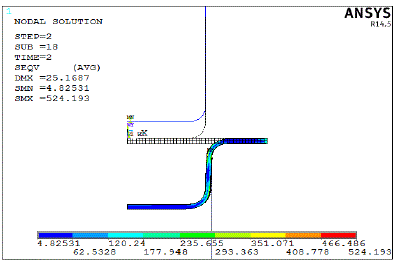 |
| The figure6 shows residual stress retained in the structure after unloading process. Maximum residual stresses are observed at the corner fillet region and at the bottom corner region. Maximum stress value is around 524.193Mpa. Minimum residual stress observed is around 4.82Mpa. Residual stress is a undesirable feature for the proper sheet metal bending process. It should be minimized for error free sheet metal products. Residual stress is the cause of crack formation and reduction in the life. It will reduce the tensile strength of the structures. So heat treatment is required to relieve this trapped stresses due to permanent deformation in the structure. |
| Calculation for Spring back: |
| Punch end Deformation : 25.5316mm |
| Retained Deformation: 25.1687mm |
| Spring back : 25.5316-25.1687=0.3629mm |
| Spring back effect =1.421% |
| 4.6: Results Comparison |
 |
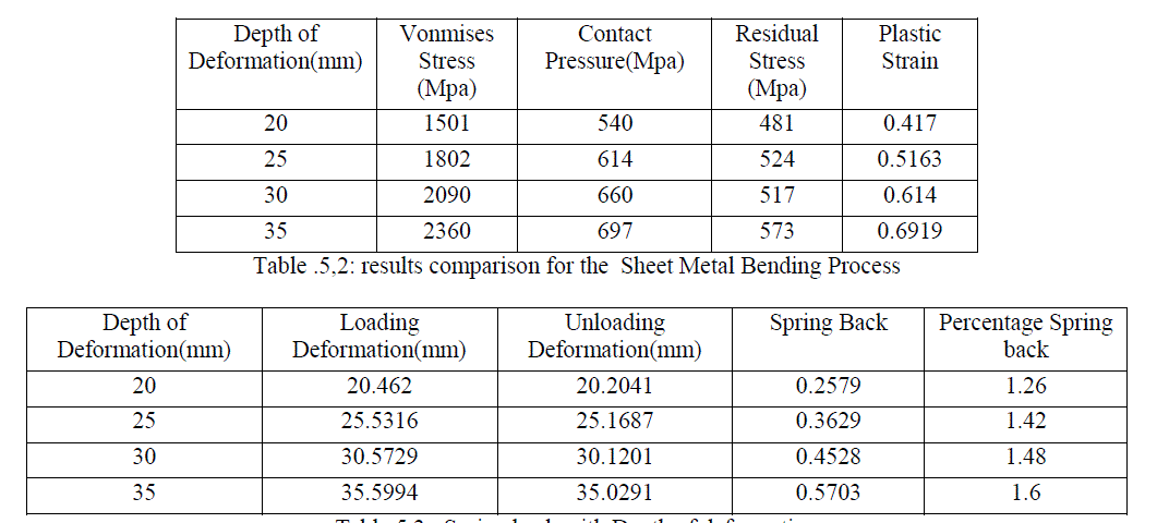
| The table4.6 shows influence of thickness on spring back phenomenon along with other important parameters. It is observed that as the thickness increases, all the other parameters like vonmises stress, residual stress, plastic strain and contact pressure are increasing. But spring back is reducing .So increasing thickness of plate is good for good sheet metal forming process. The same thing is proven through graphical plots represented below. |
| 5: Effect of Depth of sheet metal formation on spring back : |
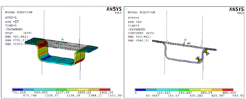
| 5.1: Case 1: Depth of sheet metal formation: 20mm |
 |
| 5.2: Results Comparison |
 |
CONCLUSION |
| Spring back phenomenon in the metal forming process has been analyzed using Finite element Analysis. Spring back phenomenon is a undesirable process in the manufacturing industry. Many parameters influence spring back phenomenon. In the present work, sheet metal thickness and depth of forming effect on spring back is analyzed using Finite element methods. The overall summary of results is as follows. |
| Initially the geometrical model is built using Ansys mixed approach |
| Plane stress with thickness approach is used for find the effect of spring back |
| The geometry is split to ease map mesh for better results |
| Plane182 element with its large deformation capability is used for analysis |
| Due to symmetry half the problem is considered. |
| Contact elements are defined between punch , sheet metal and sheet metal and die. |
| The punch target nodes are given the displacement load to solve the problem using Newton Rap son iterative procedure |
| Contac172 and Target169 elements are used for nonlinear contact analysis along with material nonlinearity with bilinear hardening of the material. |
| Total 4 cases of plate thickness are considered for analysis. The results for spring back, percentage spring back, vonmises stress, residual stress, contact pressure and plastic strains are captured. |
| The results shows plate thickness has effect on all these parameters. With the increase of the plate thickness , spring back, percentage spring back, vonmises stress, residual stress, contact pressure and plastic strains are reducing which is an important parameter to obtain better products. |
ACKNOWLEDGMENT |
| I thank my Parents, and all the Faculty members of Department of Mechanical Engineering Ghousia college of Engineering, for their constant support and encouragement. Last, but not the least, I would like to thank my peers and friends who provided me with valuable suggestions to improve my project. |
References |
|