ISSN ONLINE(2319-8753)PRINT(2347-6710)
ISSN ONLINE(2319-8753)PRINT(2347-6710)
| Vijayakumar Sureban Assistant Professor, Department of Civil Engineering, S G Balekundri Institute of Technology, Belagavi, Karnataka, Indi |
| Related article at Pubmed, Scholar Google |
Visit for more related articles at International Journal of Innovative Research in Science, Engineering and Technology
A natural slope at Padumale village is considered in this study. The concern was to check its stability as its small part has failed due to rainfall. In this study the factors of safety obtained from four methods are compared and finally slope stability is verified. Using grid method the most critical slip circle is searched. Required factor of safety is 1.2 from the consideration of intensity of damage to the lives and properties due to failure. After the analysis the overall/average factor of safety by Swedish slip circle method is 1.258, by method of slices is 1.234, by Bishopâs method is 1.231 and by Taylor stability number method is 3.47. Hence, the slope is stable as all the methods give factors of safety more than 1.2. Bishopâs method gives the factor of safety of 1.231 which is nearer value to 1.2 showing why this method is still practically used.
Keywords |
| Grid method, Most critical slip circle, Minimum factor of safety, Overall factor of safety, Average factor of safety. |
INTRODUCTION |
| Slopes can be natural, engineered/man made, infinite slopes and finite. The failure of slope is normally downward and outward. Slides/failures occur in almost every conceivable manner, slowly or suddenly, and with or without any apparent provocation, due to one or more of the reasons; erosion, rainfall, earthquakes, geological factors, external loading, construction activities such as excavation of slopes and filling of slopes, rapid drawdown, increment of pore water pressure, the change in topography. Theoretically it is possible to analysis the stability of a newly cut slope on the basis of either total or effective stresses. Since it is difficult to ascertain the distribution of pore pressures under these conditions, the total stress method has proved more successful. |
| Failure of slope may occur along a plane, regular curved surface or any nonlinear surface when a large mass of soil slides with respect to the remaining earth mass. Stability of a slope depends on the shear stress induced along the possible failure surface and the shearing strength that can be mobilized along the failure surface. Ratio of the shear strength that can be mobilized along a possible failure surface to the shear stress induced along the surface by self weight of soil mass above the failure surface and any external load is generally known as factor or safety (F). If the value of F is close to 1 the failure is incipient and the soil mass above failure surface may start sliding slowly |
MATERIALS AND METHODS |
DESCRIPTION OF PROJECT SITE |
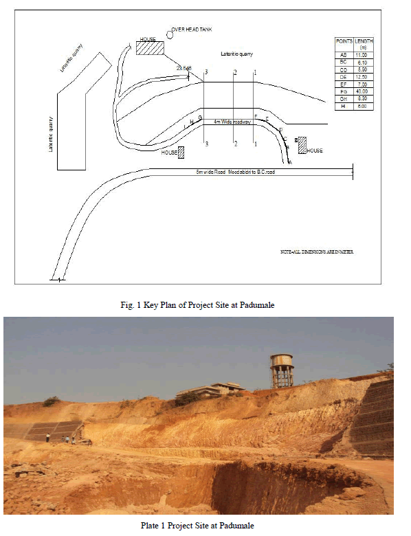
| The slope is located at Padumale village of Bantwal Cross Road of South Canara district, Karnataka, the key plan of which is shown in Fig. 1, also the photo of the same is shown in Plate 1. The geometry of slope is altered for quarrying and construction of houses and an over head water tank. The slope is cut in steps with different angles as shown in the cross section diagrams. In this study, for the stability analysis the maximum value of the slope angle (β) is considered. Basically lateritic soil is encountered in this slope. The area behind the slope is having a lateritic quarry spread over about 11 acres, three residential buildings, and one over head water tank and on to the left and right side of slope two residential houses are present. Just in front of slope the road connecting Moodbidri and Bantwal exists. The slope under consideration is having a 4 m wide connecting roadway between main road and quarry. A non-engineered retaining wall was constructed in the year 2010-11 having length of 109.25 m to retain the lateritic soil slope. In the year 2012, during rainy season the middle 40 m length of wall collapsed due to the failure of the small portion of slope. It is observed that the failure surface is approximately circular in shape; hence, in the present study the circular failure surface is used. In that collapsed portion of slope three sections as shown in Fig. 1 are considered for the slope stability analysis. |
 |
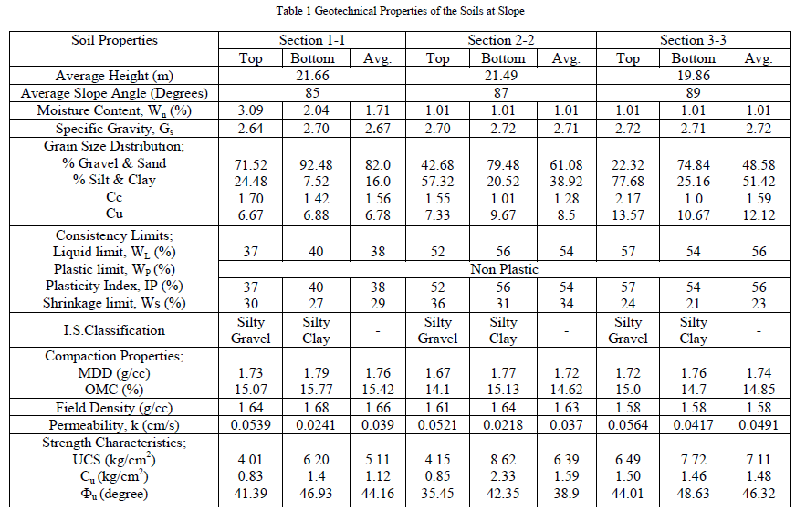
| After reconnaissance survey the disturbed soil samples at the top and bottom of every section were collected along with conducting few field tests. The major soil encountered is lateritic soil which is silty gravel in nature. The index and engineering properties of these soils are presented in Table 1, which are conducted as per relevant I.S codes. |
 |
| In the present study deterministic analysis of slope stability is used, which basically involves the calculation of the factor of safety for trial slip surfaces and the search for a slip surface, that gives critical or minimum factor of safety. The search for the critical failure surface, carried out over a number of slip surfaces, is by and large still performed by repeated trials or by the grid search method [1], as shown in Fig. 2, although it has received some attention in recent years. For example, the slope section is drawn to the suitable scale as in Fig. 5 and a typical point in the grid is having the coordinates of 2 m, 5 m from the toe of the slope, which is origin of the coordinate system. The trial slip circle is drawn from the toe and analysed for the stability by all the methods said, except for the Taylor stability number method. Such all the possible points in the grid are selected and corresponding factor of safety is obtained. Then, the slip circle in the grid having minimum factor of safety will be the critical failure surface and the corresponding factor of safety is considered for the further study. Likewise other two sections are also analysed. Then, the overall factor of safety for three dimensional slope is calculated. Such minimum factors of safety from all the methods is obtained and compared. |
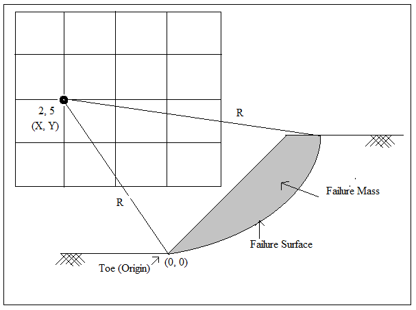 |
| Fig. 2 Grid Method of Searching Critical Slip Circle |
| In the present study the Swedish slip circle method, method of slices, BishopâÂÂs methods and TaylorâÂÂs stability number method are used. Following paragraphs brief about these methods. |
III. STABILITY ANALYSIS METHODS ADOPTED SWEDISH SLIP CIRCLE METHOD |
| The method, developed by Swedish engineers assumes that the surface of sliding is an arc of a circle [2]. Analysis is for purely cohesive soil (ÃÂu=o) and hence is the disadvantageous. The method consists in assuming a number of trials slip circle, and finding the factor of safety of each. The circle corresponding to the minimum factor safety is the critical slip circle. The factor of safety is given by following equation 1. |
| Where, MR=Resisting moment, MD=Driving moment, c= Cohesion, L=Length of arc, r=Radius of slip circle, W=Weight of the soil wedge, x = Distance of line of action of „Wâ from the vertical line passing through the centre of rotation. |
METHOD OF SLICES |
| This method is developed by Swedish engineers, which is essentially the advancement on the slip circle method and assumes that the surface of sliding is an arc of circle [3]. In order to test the stability of the, trail slip circle is drawn and the material above the assumed slip circle divided into a convenient number of vertical slices. The forces between the slices are neglected and hence are disadvantageous. The factor of safety is given by following equation 2. |
| Where, MR is Resisting moment= r (cΣ L+ tan ÃÂΣN), MD is Driving moment = rΣT, c= Cohesion, Σ L=L is Length of slip circle=2πrδ/3600, ÃÂ= Angle of internal friction, ΣN= Sum of all normal components, ΣT= Algebraic sum of all tangential components |
BISHOP’S SIMPLIFIED METHOD |
| This method was developed by [4]. A section of a slope having a sloping surface is an assumed trial circular failure surface with its centre at O. The soil mass above the failure surface is divided into a number of slices. The forces acting on each slice are evaluated from limit equilibrium of the slices. Here, the interslice forces are also considered and hence the method is advantageous. The equilibrium of the entire mass is determined by summation of the forces on each of the slices. Factor of safety is given by following equation 3. |
| Where mθ=Cosα+ [(tanÃÂ+sinα)/FS], c=Cohesion, l=Length of each arc, U=Pore water pressure, W=Weight of each slice, α=Angle suspended between weight of the slice and centre of rotation. Hence, for each trial centre of rotation, by each of the method, the factor of safety is obtained. Then, the slip circle giving minimum factor of safety is considered as critical slip circle and is used for calculating overall or average factor of safety for the slope as whole. |
OVERALL/AVERAGE FACTOR OF SAFETY |
| Since the critical factor of safety obtained by any of the methods corresponds to a section of the slope and as there is no rigorous method for determining critical factor of safety for a three dimensional slope. Following equation 4 is used to calculate the overall or average factor of safety [5]. |
| Where, F1, F2 and F3 are the critical/least factors of safety for the critical slip circles of areas A1, A2 and A3 at sections 1-1, 2-2 and 3-3 respectively. |
TAYLOR’S STABILITY NUMBER METHOD |
| The non-dimensional quantity called Taylor stability number „Nâ (refer equation 5) given by Taylor, [6] is used to study the stability of the slopes. |
 |
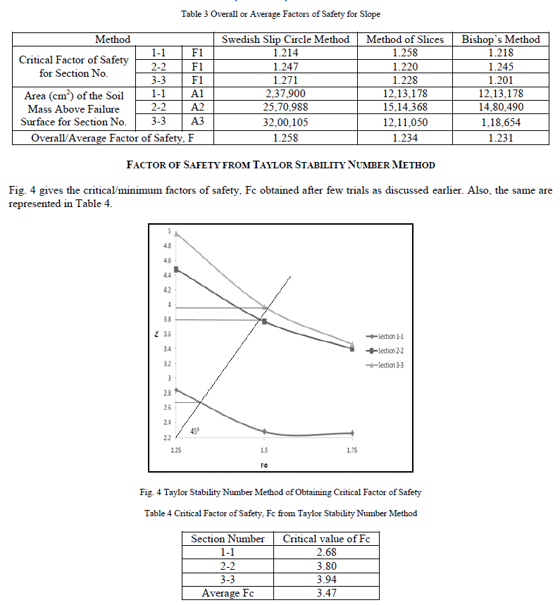
| Where, c=cohesion of soil, Fc=Factor of safety with respect to cohesion, ϒ=Unit weight of soil, H=Height of slope. The method involves assuming the value of factor of safety, Fä, with respect to friction. Then, calculating the value of mobilized friction angle, äm=ä/Fä. For this value of äm and slope angle, β we get the stability number N from either the charts or tables given by Taylor. Then using equation 5 the factor of safety with respect to cohesion, Fc is obtained. If Fc= Fä then this value of factor of safety is taken else another trial value of Fä is assumed and procedure is repeated until Fc≈Fä. Normally within two or three trials this is possible, else using following plot shown in Fig. 3 the critical/ minimum value of Fc is obtained [7]. |
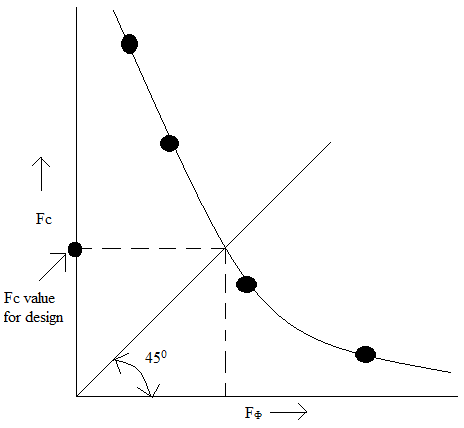 |
| Fig. 3 Method of Obtaining Fc Value for Design |
| Based on the importance of influence of slope failure on the damages, the required factor of safety are as follows in Table 2 [8]. |
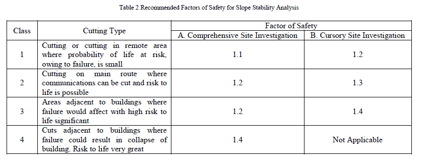 |
| Hence, in the present study the required factor of safety is 1.2 which corresponds to Class 1 and in B-column of Table 2, which is based on the field study and investigation. Therefore, in the present study the stability analysis is carried out till the factor of safety is equal or nearer to 1.2, by all the four methods. Then, for whichever centre of rotation or slip circle gives this value of factor of safety is said to be critical slip circle and then the comparison is made between the methods. |
RESULTS AND DISCUSSIONS |
| As discussed earlier, four methods namely, Swedish slip circle method, method of slices, BishopâÂÂs method and Taylor stability number method are used to arrive at the required factor of safety and for the comparison purpose. The results obtained of these are discussed one by one in the following paragraphs. Also, to search for the most critical circle that gives minimum factor of safety equal or near to 1.2 the grid method is used, which is already discussed. |
FACTORS OF SAFETY FOR SECTION 1-1 |
| The Swedish slip circle method gives the minimum factor of safety of 1.214 for the centre of rotation with coordinates (2,20), method if slices gives the minimum factor of safety of 1.258 and the BishopâÂÂs method gives the minimum factor of safety of 1.218 for the centre of rotation with coordinates (4,17). |
FACTORS OF SAFETY FOR SECTION 2-2 |
| The Swedish slip circle method gives the minimum factor of safety of 1.247 for the centre of rotation with coordinates (1, 15), method if slices gives the minimum factor of safety of 1.220 for the centre of rotation with coordinates (2,17) and BishopâÂÂs method gives the minimum factor of safety of 1.245 for the centre of rotation with coordinates (3,18). |
FACTORS OF SAFETY FOR SECTION 3-3 |
| The Swedish slip circle method gives the minimum factor of safety of 1.271 for the centre of rotation with coordinates (2, 20), method if slices gives the minimum factor of safety of 1.228 for the centre of rotation with coordinates (3,16) and BishopâÂÂs method gives the minimum factor of safety of 1.201 for the centre of rotation with coordinates (4,17). |
OVERALL OR AVERAGE FACTORS OF SAFETY |
| Using equation-4 the critical factor of safety are calculated and presented in Table 3. It can be seen from Table 3 that the overall factor of safety for the slope as a whole is 1.258 by Swedish slip circle method, 1.234 by method of slices and 1.231 by BishopâÂÂs method. This shows the BishopâÂÂs method gives the factor of safety of 1.231 which is more nearer to the required factor of safety i.e. 1.2. |
 |
CONCLUSION |
| Based on the present study the following conclusions can be drawn. |
| ï· Minimum factor of safety for section 1-1 by Swedish slip circle method is 1.214, by method of slices is 1.258 and by BishopâÂÂs method is 1.218. |
| ï· Minimum factor of safety for section 2-2 by Swedish slip circle method is 1.247, by method of slices is 1.220 and by BishopâÂÂs method is 1.24. |
| ï· Minimum factor of safety for section 3-3 by Swedish slip circle method is 1.271, by method of slices is 1.228 and by BishopâÂÂs method is 1.201. |
| ï· For the slope as a whole i.e. for three dimensional slope, it can be seen that the overall factor of safety for the slope as a whole is 1.258 by Swedish slip circle method, 1.234 by method of slices and 1.231 by BishopâÂÂs method. This shows the BishopâÂÂs method gives the factor of safety of 1.231 which is more nearer to the required factor of safety i.e. 1.2. This is why the BishopâÂÂs method is still used practically. Swedish slip circle method gives the higher value of factor safety of 1.258 which is highest of the values given by other methods, which is because of its ä=0 assumption. Also, the factor of safety of 1.234 obtained from method of slices is between the other two methods, which is due to the drawback of not considering the interslice forces. But yet still it is popular due to its simplicity. |
| ï· Form Taylor stability number method the average critical factor of safety is 3.47. |
| ï· Finally, it can be said that the slope is stable as the overall factor of safety by all the four methods is more than the required factor of safety of 1.2. But comparing the methods the BishopâÂÂs method gives value of 1.231 nearest to the required value of 1.2. Hence, it can be practically used for the stability analysis which is also accepted by the geotechnologists worldwide. |
References |
|