ISSN ONLINE(2320-9801) PRINT (2320-9798)
ISSN ONLINE(2320-9801) PRINT (2320-9798)
| T.Raja Pandi1, MKNM.Sakthi Nagaraj2, N.Panneer Selvam3 |
| Related article at Pubmed, Scholar Google |
Visit for more related articles at International Journal of Innovative Research in Computer and Communication Engineering
This paper presents A novel method used for Differential Protection in power transformer. In a power system, transformers and other electrical equipment need to be protected not only from short circuit, but also from abnormal operating conditions, such as over loading, and differential fault protection. The power transformer protective relay should block the tripping during magnetizing inrush and rapidly initiate the tripping during internal faults. Many methods have been used to discriminate magnetizing inrush from internal faults in power transformers. Most of them follow a deterministic approach, This article proposes for power transformer differential protection & the proposed algorithm are the Feed forward Back propagation Algorithm (FFBPN) as a classifier and address the challenging task of detecting magnetizing inrush from internal fault. The algorithm is evaluated using simulation performed with MATLAB. The results confirm that the FFBPN is faster, stable and more reliable recognition of transformer inrush and internal fault condition.
Keywords |
| Inrush current, differential protection, Back propagation Neural Network, MATLAB |
INTRODUCTION |
| In power systems one of the most important equipment is Power transformer. Power transformers are different in size, type, and connection. Any unscheduled repair work, especially replacement of a faulty transformer is very expensive and time consuming. Theoretically, differential protection provides the best overall protection for a power transformer. In principle, this protection scheme makes use of current difference flowing through the different terminals of transformer so as to distinguish between internal and external faults.[4] The conventional differential protection schemes might encounter difficulties and mal operations in some cases. They are not capable to distinguish between internal faults and other abnormal events in all conditions correctly. Many methods have been used to discriminate magnetizing inrush from internal faults in power transformers. The use of standard transformer differential protection for such applications is considered impossible in the protective relaying standards and practices currently applied This article proposes for power transformer differential protection and address the challenging task of detecting magnetizing inrush from internal fault. Generally, discriminate between magnetizing inrush condition and fault condition .The method consists of distinguishing magnetizing inrush and over-excitation condition from internal fault condition on the basis of waveform identification. This method was carried out by utilizing the differential current peaks, dead angle, and the length of time intervals during which the differential current is near zero. In this paper, simple decision making methods based on the Feed forward Back Propagation Neural Algorithm [9] are proposed for discriminating internal faults from inrush current. The algorithm has been developed by considering different behaviors of the differential current under internal fault and inrush condition. The MATLAB extracts the relevant features from the differential current and reduces a training data set to a lower dimension. The algorithm was proven MATLAB simulations considering distinct scenarios as changes in transformer load, source impedance, CT ratio, ruminant flux, etc RBFNN based classifier is also presented in distinguishing between magnetizing inrush and internal fault condition of power transformer. The proposed method has been observed as the best solution for power transformer differential protection. |
II. MAGNETIZING INRUSH AND INTERNAL FAULT CURRENT |
| Under normal operation circumstance, the iron core of transformer works in the unsaturation state, the relative magnetic conductivity is tremendous , and the excitation inductance of winding is also tremendous, so the excitation current is tiny, which is not more than 2%-10% of rated current. When the no-load transformer throws in or voltage recovers after external fault is cleared, because of iron core ,relative conductivity is nearly 0.[13]. Seldom parts of primary side current, most parts are into excitation inrush . So excitation inrush current only flow into one side of transformer, the amplitude is probably 6-8 times of rated current. And it causes protection equipment error operation. Internal fault is various fault occurring inside of the transformer tank, including the short circuit between the phase winding, single-phase inter-turn short circuit, single phase ground short circuits, its turn to turn short-circuit problems accounted for a large ratio.[14] Harmful to internal faults, because the high temperature electric arc short-circuit currents will not only damage the winding insulation, burning core, but will also heat insulating materials and decomposition of transformer oil , which will produce large amounts of gas which may cause the transformer tank explosion. |
III. DIFFERENTIAL PROTECTION IN TRANSFORMERS |
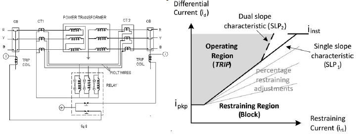
| The differential protection used for transformers is based on the principle of current circulation. This type of protection is mostly used for transformers as this responds not only to inter turn fault but also provides protection In a power transformer, the currents in primary and secondary are to be compared As these two currents are usually different, therefore the use of identical transformers will give differential current and operate the relay even under no load conditions.[10] The difference in magnitude of currents in primary and secondary of power transformers is compensated by different turns ratios of C.T.s. If T is the turn’s ratio of power transformer, |
 |
| then the turns ration of C.T.s on lv side is made T times the turn’s ration of the C.T.s on hv side. When this condition is fulfilled the secondary’s of the two C.T.s will carry same current under normal conditions.[13] And thus no current will flow through the relay and it remains inoperative. In order to understand the phase difference in the two sides consider The primary is connected in delta and the set of current transformers CT1 is connected in star, while the secondary is connected in star and the set of current transformers CT2 is connected in delta. Fig 9 illustrates the vector diagram in reference to primary and secondary sides of current transformer. IRP, IYP and IBP are the phase currents in the primary side, while IR is the line current on the same side in line R the corresponding secondary current of current transformers CT1 on the primary side is in phase with IR and is represented as IRS. the current in the secondary side of the power transformer is represented as IR, IY and IB , the phase current in the secondary winding of the current transformers CT2 is represented as I’R, I’Y and I’B the current in pilot wire of CT2 is represented as IRS. |
IV. POWER SYSTEM SIMULATION |
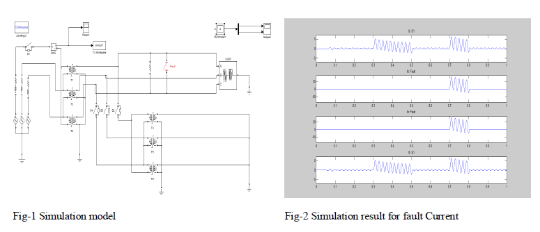
| To obtain the required current signals for investigation of the merit of the proposed algorithm, a part of a power system consisting of a power transformer and relevant CTs with transmission lines on the both sides of the transformer are modeled using MATLAB SIMULINK software that is shown in Fig. . So the required current signals for a digital differential protection can be provided. The proposed power system consists of a 500-MVA and 400/230-kV transformer and the distributed model for the transmission lines is used. A long 400-kV line in parallel with the transformer distorts the faulty current waveform. Different cases of inrush current and fault current are simulated. Different cases of inrush current are simulated by varying those major parameters that influencing the characteristics of this current. These parameters are the residual core flux of single phase transformers , the voltage angle of switching phase a, switching in the case of close or open secondary, the high or low power supply connected to transformer and knee of the core magnetic characteristic. Different cases of fault currents are also simulated where the major factors affecting the characteristics of the current are considered. These factors include the type of fault and load condition. The results of application of the proposed algorithm for different conditions of inrush current have been summarized in 6.3.1. This section shows the values of X and Y of different phases during shorter than a quarter a cycle following waveform distortion due to different inrush current. The results of application of the proposed algorithm for internal fault conditions .Simulations have been carried out for different faults in no-load and on-load of power system. In addition to the fault and inrush currents cases, it is necessary to study the merit of the algorithm for simultaneous fault and switching |
V. SIMULATION & RESULT |
 |
VI. PROPOSED ALGORITHM - BACK PROPAGATION ALGORITHM |
| Back propagation is a form of supervised learning for multi-layer nets, also known as the generalized delta rule. Error data at the output layer is back propagated to earlier ones, allowing incoming weights to these layers to be updated. It is most often used as training algorithm in current neural network applications. The back propagation algorithm was developed by Paul Werbos in 1974 and rediscovered independently by Rumelhart and Parker. Since its rediscovery, the back propagation algorithm has been widely used as a learning algorithm in feed forward multilayer neural networks. |
| Before starting the back propagation learning process, we need the following: |
| • The set of training patterns, input, and target |
| • A value for the learning rate |
| • A criterion that terminates the algorithm |
| • A methodology for updating weights |
| • The nonlinearity function (usually the sigmoid) |
| • Initial weight values (typically small random values) |
VII. BACK PROPAGATION PROCESS |
| The process then starts by applying the first input pattern Xk and the corresponding target output Tk. The input causes a response to the neurons of the first layer, which in turn cause a response to the neurons of the next layer, and so on, until a response is obtained at the output layer |
 |
| That response is then compared with the target response, and the difference (the error signal) is calculated. From the error difference at the output neurons, the algorithm computes the rate at which the error changes as the activity level of the neuron changes. So far, the calculations were computed forward (i.e., from the input layer to the output layer). Now, the algorithms steps back one layer before that output layer and recalculate the weights of the output layer (the weights between the last hidden layer and the neurons of the output layer) so that the output error is minimized. The algorithm next calculates the error output at the last hidden layer and computes new values for its weights (the weights between the last and next-to-last hidden layers). |
| The algorithm continues calculating the error and computing new weight values, moving layer by layer backward, toward the input. When the input is reached and the weights do not change, (i.e., when they have reached a steady state), then the algorithm selects the next pair of input-target patterns and repeats the process. Although responses move in a forward direction, weights are calculated by moving backward, hence the name back propagation. |
VIII. IMPLEMENTATION OF BACK PROPAGATION ALGORITHM |
| The back-propagation algorithm consists of the following steps: |
| Each Input is then multiplied by a weight that would either inhibit the input or excite the input. The weighted sum of then inputs in then calculated |
| First, it computes the total weighted input Xj, using the formula: |
| Where yi is the activity level of the jth unit in the previous layer and Wij is the weight of the connection between the ith and the jth unit. |
| Then the weighed Xj is passed through a sigmoid function that would scale the output in between a 0 and 1. |
| ï· Next, the unit calculates the activity yj using some function of the total weighted input. Typically we use the sigmoid function: |
| Once the output is calculated, it is compared with the required output and the total Error E is computed. |
| ï Once the activities of all output units have been determined, the network computes the error E, which is defined by the expression: |
| where y j is the activity level of the ith unit in the top layer and dj is the desired output of the ith unit. Now the error is propagated backwards. Compute how fast the error changes as the activity of an output unit is changed. This error derivative (EA) is the difference between the actual and the desired activity |
| Compute how fast the error changes as the total input received by an output unit is changed. This quantity (EI) is the answer from step 1 multiplied by the rate at which the output of a unit changes as its total input is changed. |
| Compute how fast the error changes as a weight on the connection into an output unit is changed. This quantity (EW) is the answer from step 2 multiplied by the activity level of the unit from which the connection emanates. |
 |
| Compute how fast the error changes as the activity of a unit in the previous layer is changed. This crucial step allows back propagation to be applied to multi-layer networks. When the activity of a unit in the previous layer changes, it affects the activities of all the output units to which it is connected. So to compute the overall effect on the error, we add together all these separate effects on output units. But each effect is simple to calculate. It is the answer in step 2 multiplied by the weight on the connection to that output unit. |
 |
IX. TESTING PERFORMANCE |
 |
X. CONCLUSION |
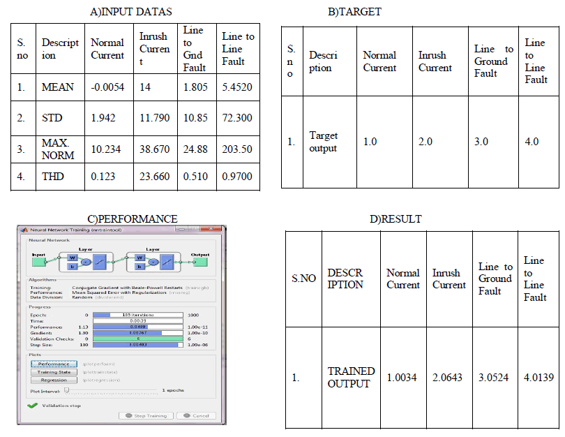
| This work presents a new approach in differential protection for power transformer vastly improved performance over conventional techniques. The conventional harmonic restraint technique may fail because high second harmonic components are generated during internal faults and low second-harmonic components are generated during magnetizing inrush with such core materials. In the previous algorithm was used for Radial Basis Function Neural Network approach. It does not require choosing any coefficient or threshold values. It was analyzed by the taking the values are magnitude parameter of the inrush & fault current. But sometimes the magnitude of the inrush & Fault current has same, so classification performance error was presented. In this phase to improve the performance & rectify error by analyzing of Mean , Standard Deviation , Maximum Norm & THD values are taken from the inrush & fault current. And also approach by the new algorithm of Feed Forward Back Propagation Neural algorithm was performed. The ability of the new method will demonstrate by simulating various cases on a typical power system and the proposed algorithm is also tested data collected from a simulation model. In this new algorithm is performance was very vital. The proposed approach is considered a general tool because it can be easy implemented on the popular MATLAB software. Moreover, the approach is considered a flexible tool. We expect this work providing useful reference to electric power industry |
References |
|