ISSN ONLINE(2278-8875) PRINT (2320-3765)
ISSN ONLINE(2278-8875) PRINT (2320-3765)
N.Lakshmipathy1, Ch.S.N.Murthy2, M. Aruna 3
|
| Related article at Pubmed, Scholar Google |
Visit for more related articles at International Journal of Advanced Research in Electrical, Electronics and Instrumentation Engineering
In surface mines where natural light is not available especially during night hours artificial light is provided for better seeing, which facilitates increased production, reduce workers fatigue, protect their health, eyes and nervous system, and reduce accidents. One major problem in surface mine lighting is continuous changing of task place, including roadways. Because of this reason, it is difficult to provide any kind of long term permanent structure for illumination. Hence, the shifting of lighting installations at regular interval is very much necessary, so as to ensure required light level, as per the lighting standards specified by various regulatory bodies.
INTRODUCTION |
| In mines particularly haul road lighting is a critical concern for mines authorities. Because compared to other locations of mines illuminating haul roads is quite tedious and complex in nature. This is mainly because the haul roads are continuously moving, which requires regular shifting of light poles/lamps. Inefficient lighting wastes significant financial resources each year and also poor lighting creates unsafe conditions. Energy efficient technologies and proper design of lighting system can cut haul roads lighting costs dramatically often by 25-60 % (NYCGP 2009) and also it improves safety and comfort of miners. A well-designed, energy-efficient haul road lighting system should permit users to travel at night with good visibility, in safety and comfort, while reducing energy use and costs and enhancing the appearance of the neighborhood. Conversely, poorly designed lighting systems can lead to poor visibility or light pollution, or both. Quite often, haul roads lighting is poorly designed and inadequately maintained (e.g., there are large numbers of burned-out lamps), and uses obsolete lighting technology—thus consuming large amounts of energy and financial resources, while often failing to provide high-quality lighting (USAID June 2010). The Bureau of Energy Efficiency, based on Central Electricity Authority statistics, has estimated gross energy consumption for public lighting to be 6,131 million kWh in India for the years 2007-2008. |
| In order to provide a comfortable light level in the mines, as per the prevailing guidelines, a systematic illumination survey needs to be conducted. In this regard, as a case study, an illumination survey was conducted in a large mechanized surface coal mine of a country. As a In order to assess the status of illumination in surface coal mines, systematic illumination is needed to be conducted using appropriate statutory guidelines, so that effective control measures can be taken. Keeping this in view, illumination study in of the mechanized surface coal mine is considered for case study. |
| Then an attempt is made to design a program that gives a real time survey data of illumination in mines. The program is developed on the MATLAB platform. The program gives a real time lux data, 3-D charts, 3-D graph, 2-D plot and also source comparison table. The program also read out the height of the mounting also. |
ENERGY-EFFICIENT LIGHTING |
| In the last few years, technological advancements in lighting have led to the development of energy-efficient lighting systems that consist of one or more components as listed below: |
| Low loss ballasts |
| Constant wattage, high intensity electronic ballasts |
| Energy-efficient luminaries |
| Better monitoring and control mechanisms |
| Guidance for lighting of public streets, roads, haul roads and highways is provided in the Bureau of Indian Standard (BIS, 1981). The most common reasons for inefficient haul road lighting systems in surface mines are: |
| Selection of inefficient luminaries |
| Poor design and installation |
| Poor power quality |
| Poor operation and maintenance practices |
| There is tremendous potential to improve lighting quality and operation and maintenance (O&M) practices while reducing energy consumption and greenhouse gas emissions-through energy-efficient retrofits (NYSERDA 2002). The efficiency of lighting system can also be significantly improved by selecting appropriate optics for the luminaries as well as ensuring proper design parameters, like mounting height, overhang, tilt angle etc. during installation of light sources. |
A) Lamp Technology |
| The most important element of the illumination system is the light source. An electric light source is a device, which transforms electrical energy or power (in watts), into visible electromagnetic radiation or light (lumens). The rate of converting electrical energy into visible light is called “luminous efficacy” and is measured in lumens per watt (NYCGP 2009). It is the principal determinant of the visual quality, cost and energy efficiency aspects of the illumination system (NYCGP 2009). |
B) Advantages of Energy-Efficient Lighting System |
| By adopting new and energy-efficient technologies and introducing procurement practices that promote the purchase of these technologies, large energy and cost savings can be achieved (NYCGP 2009). Considering the variable power quality conditions, selection of lamps that operate over a wide range of power parameters would significantly reduce the replacement costs of the lamps by reducing the failure rate, although it may entail a high initial investment cost. Further, good lighting can enhance visibility and safety, and helps to reduce consumption of electricity and reduction in costs, so as to free up resources for other pressing needs, thereby contributing to the improvement of the overall quality of life. |
SYSTEM OF LIGHTING IN SURFACE MINES |
| One of the important aspects of designing lighting system is to determine the optimum position of the luminaries and the capacity of the light sources. Sources may be mounted on poles, towers and masts as per the convenience of mining operations. The modern heavy-duty face machinery dictate increasing in the bench height, forcing individual face lighting system, mounted on tripods. Individual lights may also be provided at active zones in addition to the general lighting scheme. In general, luminaries are mounted on: |
| Machines used in the mines |
| Movable telescopic as well as tiltable trolley mounted lighting mast |
| Low height (1.5- 2.0 m) tripods for spot face lighting |
| Towers erected on planned locations outside the blasting zone |
| Generally lamps mounted on tripods are used near the loading machines at the face. The cable wheel may be placed at one end, so that the cable can be stretched along the length of the face. Telescopic lighting mast (also called mobile lighting towers) either self-powered or towable type is used at the place, where more number of activities is carried out simultaneously. In some critical areas such as dumpyards, stackyards etc. where the dumping activities and vehicle movement are being carried out, it is advisable to go for movable lighting system connected to the main lighting scheme (Sigma Search Lights 2000). |
A) Haul Road Illumination |
| Among all available lamp mounting systems, swage (insertion) type steel tubular poles are commonly used for haul road and other general lighting in surface mines. The specifications of light poles are given in Bureau of Indian Standard (BIS, 1981). In mines light poles are erected on single side of haul roads, i.e. along the length of crest of the face. In most of the Indian mines the height of the poles vary from 7 m to 12 m, with the angle of the light arm vary from 35º to 70º vertically upward with horizontal. |
B) Methods for Calculating Illumination |
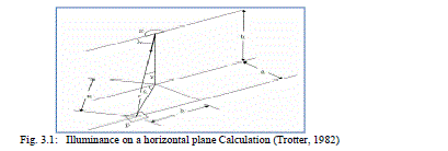
| The fig 3.1 gives to determine the Illuminance on a horizontal plane, to calculate the Illuminance first step is to determine how much flux is to be received. |
 |
| where |
| MF = Maintenance factor (Light Loss Factor LLF) |
| UF = Utilization factor |
| The maintenance factor gives an estimate of how lighting conditions will deteriorate through use. Some factors are |
| · Dust and dirt inside luminaire surfaces. |
| · Aging of light bulbs emitting less light. |
| Cleaning of room surfaces, e.g. ceiling without detailed knowledge of a maintenance plan, one sets MF = 0.80. where, |
| ‘S’ is the source. |
| ‘P’ is the point at which illuminance is to be measured. |
| ‘a’ is the width of the road. |
| ‘b’ is the width of the road along C-plane. |
| ‘γ' ‘is the angle between the vertical and the line joining inclined distance from the source to the point of measurement. |
| ‘h’ is the height of the source from ground. |
 |
FORMULAE |
| AREA (A) =LENGTH * BREADTH. |
| IN CLINATION ANGLE(COS ÃÂ)=(x/r) |
| INTENSITY(I)=POWER/(4**AREA) |
| ANGLE GAMMA= COS(-1)(h/r) |
| ANGLE C=TAN (-1)(a/b) |
| HORIZONTAL ILLUMINATION=(I*COSÃÂ*UF)/(A2)*IMF |
| VERTICAL ILLUMINATION=(I*SIN ã*UF)/(A2)*IMF |
| UNIFORMITY RATIO=(MAX ILLUMINATION/MIN ILLUMINATION). |
C) MATLAB Aided Design of Lighting System |
| The computer programs employed for the calculation of the above illuminance, luminance can be structured various degrees of sophistication. MATLAB is a high-performance language for technical computing. It integrates computation, visualization, and programming in an easy-to-use environment where problems and solutions are expressed in familiar mathematical notation. |
| Typical features include: |
| Math and computation. |
| Algorithm development. |
| Modeling, simulation, and prototyping. |
| Data analysis, exploration, and visualization. |
| Scientific and engineering graphics. |
| Application development, including Graphical User Interface building. |
D) Field Study |
| As a case study, an illumination survey was carried in a mechanized surface coal mine, where horizontal and vertical lux levels were measured using digital luxmeter. This table indicates the illuminance lux levels measured at each grid point using digital Luxmeter for parameters such as Power rating of the Source, height of the tower, Width of the road, Length of the measuring Field, Tilt angle Overhanging extension, etc as indicated under the test conditions |
PRACTICAL OUTPUT |
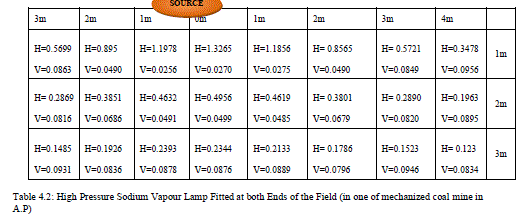
| Table 4.1: High Pressure Sodium Vapour Lamp Fitted At the Center of the Field (in one of mechanized coal mine in A.P) |
| Source: High Pressure Sodium Vapour Lamp |
| Height of Tower: 6m |
| Width of the Road: 3m |
| Length of the measuring Field: 7m |
| Tilt angle: 12 degree |
| Overhanging extension: 2m |
| Power: 250w |
| H : Horizontal reading and V: Vertical reading |
 |
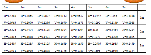
| Source: High Pressure Sodium Vapour Lamp |
| Height of tower: 6m |
| Width of the road: 3m |
| Length of the measuring field: 7m |
| Tilt angle: 12 degree |
| Overhanging extension: 2m |
| power: 250w |
 |
A) Flowchart of the program |
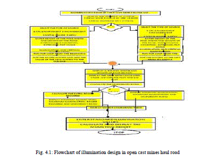
| Figure 4.1 shows the flowchart for Illumination Design in MATLAB for an surface coal Mine Haul Road, taking the parameters, such as the types of sources (1:CFL 2: Florescent 3: Incandescent 4: Metal halides 5: High pressure sodium vapour ); it gives whether the source is fitted at the center of the field, total height of source from ground, total width of the road, total length of the measuring field, enter 1: overhanging 2: beyond kerb 3: above the kerb, enter the tilt angle in degree, enter the extension of source, etc. are the data’s governing for Horizontal reading and Vertical reading, Uniformity ratio, etc. the flow chart indicates if the Uniformity ratio is not equal to 0.3, it checks for the for loop for how much is the extra power needed to get Uniformity ratio to be equal to 0.3. |
 |
MATLAB OUTPUT |
| A) Design parameters of a single High pressure sodium Vapour lamp fitted at the center of the field |
| Illumination of road lighting of open cast mines |
| Enter the number source 1: Single source 2: Double source = 1 |
| Illumination of road lighting with single source |
| Enter the type of sources 1: CFL 2: Fluorescent 3: Incandescent 4: Metal halides 5: High pressure Sodium Vapour: = 5 |
| High pressure Sodium Vapour lamp Source fitted at the center of the field |
| Total height of Source from ground in m=6 |
| Total width of the Road in m=3 |
| Total length of the measuring field in m=7 |
| Enter 1: Overhanging 2: beyond Kerb 3: above the Kerb 1 |
| Enter the tilt angle in degree =12 |
| Enter the extension of source in m=2 |
| Enter 1: Lux data for vertical illumination |
| Distance along the z-plane A =1 |
| Distance along the x-plane B =1 |
| A: B Ratio = 1 |
| Utilization Factor (UF) = 0.8000 |
| Inverse Maintenance Factor (IMF) =1.2000 |
Program output |
 |
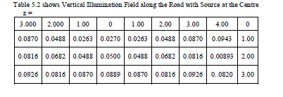
| After comparing from Table 4.1 of practical output with Table 5.1 of MATLAB output for Horizontal Illumination Field along the Road with Source at the Centre % Error was found to be = ± 2-5 |
| After comparing from Table 4.1 of practical output with Table 5.2 of MATLAB output for Vertical Illumination Field along the Road with Source at the Centre % Error was found to be = ± 2-5 % |
 |
 |
 |
| Table 5.3, 5.4 shows the C – Values and Gamma values for illumination field along the Road with Source at the centre |
| Max_Illumination =1.3365, |
| Min_Illumination = 0.1153 |
| Uniformity Ratio = 0.0863 |
| To get a Uniformity ratio of = 0.3 |
| Required Power = 150.2763 |
| Enter 1: Horizontal 3D = 1 |
| Enter 2: Vertical 3D = 2 |
| Enter 3: plot = 3 |
 |
| Construction of tower and source calculation led as per standardize value and requirement enter the standard illumination required in lux = 10. The Fig.5.1 shows the Horizontal illumination at variable distance with source at the center for a 100w Compact Fluorescent Lamp (CFL) mounted at a height of 6.0m with the tilt angle 12 degrees. The Fig.5.2 shows the Vertical illumination at variable distance with source at the center for a100w CFL mounted at a height of 6.0m with the tilt angle 12 degrees. The Fig.5.3 shows the 3-D plot for horizontal illumination at variable distance with source at the center for a100w CFL mounted at a height of 6.0m with the tilt angle 12 degrees. The Fig.5.4 shows the 3-D plot for vertical illumination at variable distance with single source at the center for a100w CFL mounted at a height of 6.0m with the tilt angle 12 degrees. |
 |
 |
 |
 |
 |
| The Graph.5.1 shows the 2-D plot for horizontal and vertical illumination at variable distance with source at the center for a100w CFL mounted at a height of 6.0m with the tilt angle 12 degrees. |
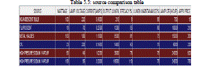
| From the literature survey the Table 5.5: shows the parameters such as source wattage, its operating voltage, current rating, output lumens, efficacy, source life and its approximate cost in the source comparison table for 1) CFL 2) Fluorescent 3) Incandescent 4) Metal halides 5) high pressure sodium vapour. |
B) Design parameters of a High pressure sodium vapour lamp fitted at both end of the field |
| Illumination of road lighting of open cast mines |
| Enter the number source = 1: Single Source 2: Double Source =2 |
| Illumination of Road Lighting with Double Source |
| Enter 1: CFL 2: Fluorescent 3: Incandescent 4: Metal halides 5: High Pressure Sodium Vapour: = 5 |
| High pressure Sodium Vapour Lamp |
| Two Sources fitted at the Field |
| Total height of Source from ground in m =6 |
| Total width of the road in m =3 |
| Total length of the Measuring Field in m = 7 |
| Enter 1: Overhanging 2: Beyond Kerb 3: Above Kerb 1 |
| Enter the tilt angle in degree =12 |
| Enter the extension of source in m =2 |
| Enter 1: Lux data for vertical Illumination: 1 |
| Distance along the z-plane A =1 |
| Distance along the x-plane B =1 |
| A: B ratio, Ratio =1 |
| Utilization factor |
| UF = 0.8000 |
| Inverse Maintanance factor |
| IMF =1.2000 |
| Table 5.6 shows Horizontal Illumination field along the road with two sources |
 |
| After comparing from Table 4.2 of practical output with Table 5.6 of MATLAB output for Horizontal Illumination Field along the Road with two Source at the Centre % Error was found to be = ± 2-5 |
 |
| After comparing from Table 4.2 of practical output with Table 5.7 of MATLAB output for Vertical Illumination Field along the Road with two Source at the Centre % Error was found to be = ± 2-5 |
 |
| Table 5.3, 5.4 shows the C – Values and Gamma values for illumination field along the Road with two Sources at the centre |
 |
| UNIFORMITYRATIO |
| Max_Illumination =1.4088, |
| Min_Illumination = 0.2659 |
| Uniformity Ratio =0.1887 |
| To get a Uniformity Ratio of =0.3 |
| Required Power =158.4040 |
| Enter 1: Horizontal 3D = 1 |
| Enter 2: Vertical 3D = 2 |
| Enter 3: Plot = 3 |
C) Construction of Tower and Source Calculation as Per Standardize Value and Requirement |
| Enter the standard Illumination required in lux = 20 |
| Enter the Wattage of light in watt =150 |
| Enter the standard angle required in Degree = 10 |
| Enter the Width of the Road in m =3 |
| Mounted_height = 4.6673 |
 |
 |
| The Fig.5.5 shows the Horizontal illumination at variable distance with two sources for a100w Compact Fluorescent Lamp (CFL) mounted at a height of 6.0m with the tilt angle 12 degrees. The Fig.5.6 shows the vertical illumination at variable distance with two sources for a100w CFL mounted at a height of 6.0m with the tilt angle 12 degrees. The Fig.5.7 shows the3-D plot for horizontal illumination at variable distance with two sources for a100w CFL mounted at a height of 6.0m with the tilt angle 12 degrees. tilt angle 12 degrees. The Fig.5.8 shows the 3-D plot for vertical illumination at variable distance with two sources at the center for a100w CFL mounted at a height of 6.0m with the tilt angle 12 degrees Graph.5.2 shows the 2-D plot for horizontal and vertical illumination at variable distance with two sources for a100w CFL mounted at a height of 6.0m with the tilt angle 12 degrees. |
 |
| Fig-5.7: 3-D plot for horizontal illumination at variable distance with two sources |
 |
| Fig-5.8: 3-D plot for vertical illumination at variable distance with two sources |
 |
| Graph-5.2: 2-D plot for horizontal and vertical illumination |
ANALYSIS |
| It has to be borne in mind that optimum design achieved is valid only for the chosen illumination standards. In fact the design parameters i.e. spacing and number of poles will vary with the change in standards. In overall the experimental study reveals that height of mounting with tilt angle is very important to achieve all the required lighting standards at the same time. |
| In general, for surface coal mine lighting luminaries are fitted giving some tilt angle. This restricts the direct application of fundamental lighting law namely, the cosine law. Since the illuminating surface is not perpendicular to the axis of luminaire. The mathematical model has been developed keeping this aspect in view. The computer program developed on MATLAB takes care of the tilt effect for each and every grid point of illuminating surface. The program computes the light level at any given point taking into consideration of the cumulative effect of the light sources. |
CONCLUSION |
| Minimum height of lighting installation, in general, should be governed by HEMM of maximum height moving on the road. Pole height may be varied from 12 to 16 meters for haul roads of around 12 meters width, which is usually prevailing in Indian surface coal mines. |
| Lamp selection is made mainly based on efficacy and suitability to each situation. Because of long life and efficient penetration character in dusty and foggy environment high pressure sodium vapor lamps are giving very good performance in surface coal mine lighting. For small projects lighting can be designed based on optimum energy consumption. No doubt, energy efficient design has a tremendous impact on cost. But the final decision on which lighting system is to be installed should be based on total cost, which should include the initial cost of the installation as well as its operating and maintenance cost. |
References |
|