ISSN ONLINE(2319-8753)PRINT(2347-6710)
ISSN ONLINE(2319-8753)PRINT(2347-6710)
B.Iftekhar Hussain1, Mir Safiulla2, Mohamed Ali3, G.Suresh4
|
| Related article at Pubmed, Scholar Google |
Visit for more related articles at International Journal of Innovative Research in Science, Engineering and Technology
Injection moulding is a manufacturing process for producing plastic parts from both thermoplastic and thermosetting plastic materials. The aim of this paper is to model, extract core–cavity and develop injection moulding tool for manufacturing an object. The part modelling, Core–Cavity design is done using PLM software Pro/ENGINEER 4.0. Mould base design is done according to HASCO standards. The plastic flow analysis is performed. NC code for fabricating the mould is generated using Vericut software. The unit cost to make a component is estimated including all the costs like material cost, tooling cost, machining cost etc.
Keywords |
| Injection Moulding, plastic, core-cavity, cost, tooling, machining |
INTRODUCTION |
| Injection molding is a manufacturing process where material is fed into a heated barrel, mixed, and forced into a mold cavity where it cools and hardens to the configuration of the mold cavity. After a product is designed, usually by an industrial designer or an engineer, molds are made by a mould maker (or toolmaker) from metal, usually either steel or aluminum, and precision-machined to form the features of the desired part. Injection molding is widely used for manufacturing a variety of parts, from the smallest component to entire body panels of cars. The object for study taken is power box panel which is used in earth movers to control the power circuit. It has top cover, front cover, back cover and side panel. The paper provides insight on power box side panel, its modeling, mould flow analysis, fabrication and cost estimation. |
II. LITERATURE SURVEY |
| Injection moulding is an area where continuous work is being carried out for a long period of time. An attempt has been made to develop a prototype intelligent design system for injection moulds based on usage of internet based technologies as in [3]. Studies have been made for understanding the effect of thermal residual stress and warpage [4]. Studies revealed the optimum parameters that minimize the warpage in injection mould using Taguchi approach [5]. Researchers had studied cooling channels in the mould and its affect on final product temperature to know the shrinkage rate distribution [6]. Efforts have been made to build a methodology for process selection and manufacturability evaluation of computer based rapid tooling for producing injection moulds [7]. Attempts were made to develop a model so as to have the lowest life cycle cost in the manufacture of injection moulds [8]. Previous results show that cavity pressure and mold temperature are the dominant factors determining the quality of the final product in plastic injection molding [9]. The present studies aims at designing an injection mould tool for fabricating power box side panel and study the parameters by performing the flow analysis on the part. It provides an insight into manufacturability of the mould. It also depicts the methodology for arriving at the unit cost of the product including the tooling costs. |
III. MATERIALS AND METHODS |
| A. Material Power boxes are metal or plastic enclosures used as housings for wiring connections. The material proposed for the manufacturing of power box panel is Acrylonitrile Butadiene Styrene (ABS) plastic to have, ï· resistant to corrosion ï· protection against dust, fire and moisture for the interior of power box ï· low contact resistance ï· durability ï· flame retardant ï· high heat resistance ï· high impact resistance ï· manufacturability ï· dimensional stability |
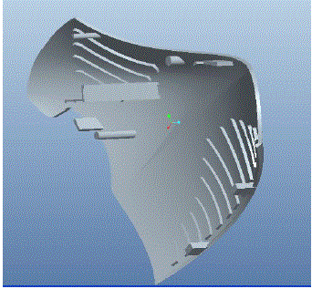
| B. Methodology The 3D CAD model of the power box panel modeled using Pro/ENGINEER 4.0 is shown in figure 1. It is designed as per HASCO standards by providing shrinkage allowance of 1.25%, draft angle of 10 along core side and 1 mm radius in all sharp corners [11]. |
 |
| Fig 1. Model of power box side panel |
| Mould flow analysis is carried out to reap the following benefits. ï· Optimize the part wall thickness to achieve uniform filling patterns, minimum cycle time and lowest part cost. ï· Identify and eliminate cosmetic issues such as sink marks, weld lines and air traps. ï· Determine the best injection locations for the part design. Pro/ENGINEER Plastic Advisor is used to simulate mould filling for injection moulded plastic parts. Advanced features are also used to provide valuable manufacturability insight that can significantly reduce late-cycle design changes and mould reengineering costs. Vericut 6.2.1 is used to study the manufacturing of mould and its allied difficulties therein. |
IV. RESULTS AND DISCUSSION |
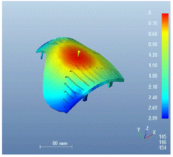
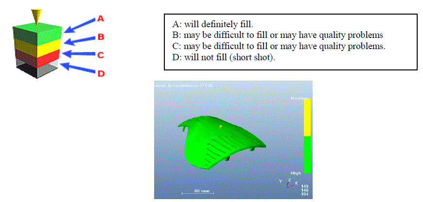
| The following results are embodied after conducting the study. The fill time result is shown in figure 2 which depicts the flow path of the plastic through the part by plotting contours which join regions filling at the same time. The maximum fill time is found to be 2.99 sec. The confidence of fill result is displayed in figure 3 which depicts the probability of a region within the cavity filling with plastic at conventional injection moulding conditions. It is found that the material will definitely fill in the entire cavity based on the temperature and pressure. The Pressure Drop result shown in figure 4 is a contour plot showing the pressure required to flow the material to each point in the cavity. The pressure drop is found to be 27.42 MPa. The Injection Pressure result shown in figure 5 is a contour plot of the pressure distribution throughout the cavity at the end of filling. The maximum value is at the Injection Location and the minimum is at the last point of the cavity to fill. The flow front temperature result shown in figure 6 indicates the region of lowest temperature (blue colour) through to the region of highest temperature (red colour). The result shows the changes in the temperature of the flow-front during filling and is found to be 225.410C. The quality prediction results are shown in figure 7. In these results, red colour represents unacceptable quality, yellow colour represents acceptable quality and green colour represents preferred quality. The results shown clearly indicate that the preferred quality can be obtained with little chance of acceptable quality at few regions. The non-representation of red colour clearly depicts that the design is safe with respect to quality. The exploded view of the entire mould assembly is depicted in figure 8. The different status of machining the mould is simulated and is depicted in Fig. 9 & Fig. 10 for core and cavity respectively. |
 |
| Fig. 2 Fill time results showing the flow path of the plastic through the part |
 |
| Fig. 4 Pressure Drop results showing the pressure required to flow the material to each point in the cavity |
| Fig. 5 The Injection Pressure result showing the pressure distribution throughout the cavity at the end of filling |
 |
 |
 |
| Total cost per component = Material cost + Mould cost + Production cost + Packing charges = 21+0.96+5.56+5= Rs 32.52 |
VI. CONCLUSION |
| The complete injection mould tool is designed for fabricating power box side panel by considering the runner design, over flow design, cooling channel design etc. using Pro/Engineer software. The plastic flow analysis is carried out using Plastic Advisor of Pro/Engineer. All the results viz. fill time, confidence of fill, injection pressure, pressure drop, flow front temperature, quality prediction are analysed. CNC manufacturing program is generated using VERICUT. The cost of each power box side panel is estimated as Rs.32.52. |
References |
|