International Journal of Innovative Research in Science, Engineering and Technology
ISSN ONLINE(2319-8753)PRINT(2347-6710)
ISSN ONLINE(2319-8753)PRINT(2347-6710)
| Mohan.k¹, Arun.L.R2 and Guruprasad.B.S3 PG Scholar, The oxford college of engineering, Bangalore, India1. Assistant professor, The oxford college of engineering, Bangalore, India2. PG scholar, The oxford college of engineering, Bangalore, India3. |
| Related article at Pubmed, Scholar Google |
Visit for more related articles at International Journal of Innovative Research in Science, Engineering and Technology
The present work is concerned to identify the root cause analysis for the crack generation in an Attemperator and suggesting the optimal solution in order to meet the required number of fatigue life of the Attemperator and henceforth to maintain the damage index value less than one. In this project, nonlinear material properties are considered for the analysis from ASME/EN pressure vessel standards and EN standards are used to estimate the fatigue life of the component. In the present scenario, the design-by formula approach does not control fatigue damage since such damage is caused by local stress and strain conditions which are not considered in the membrane stress evaluation. The local maximum range of von Mises stress and stress intensity and the thermal strain are the most important determinant of low cycle fatigue damage, with the local stress conditions contributing a mean stress effect.
Keywords |
| Attemperator, nozzle, thermal expansion, thermal gradient, stress, length of the stem |
INTRODUCTION |
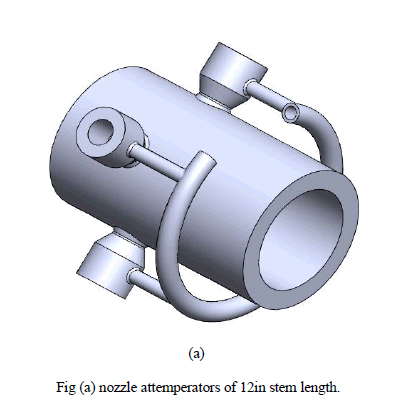
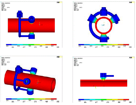
| Attemperator is design to handle high temperature gradient between cold water injected and hot stream flowing through it [1]. Fatigue failure related problems with attemperator have become more relevant in recent years due to higher cycling of power plants. Severity of thermal fatigue failure primarily depends on the temperature gradient existing in the attemperator and the physical design of it [3]. Sudden change in material thickness or non-symmetric design leads to significant increase in thermal stress and reduction in thermal fatigue life of the attemperator [1]. This paper seeks to determine the root cause of field failure (appearance of cracks) observed at the weld of spray nozzle connection with main stream pipe for attemperator. Fig-1 gives the snap shot of two nozzles attemperator of water leg (stem) length of 12in. In the traditional attemperator, nozzles are connected to the main steam pipe on a circle (no eccentricity among nozzles). In the attemperator, two nozzles were placed eccentrically or with offset as shown in figure to increase de-superheating performance. Water was supplied using an angled water leg & a single water connector at the end. |
| Three nozzles which is 120° apart leads to differential thermal expansion in the nozzle assembly. In this scenario, length of the water leg plays an important role in controlling the thermal stress in the weld region. If water leg length is short, entire assembly becomes stiff. An unequal thermal expansion at nozzle connections leads to high thermal stress as water leg is not providing any additional flexibility due to short length. Longer water leg length provided flexibility in the assembly and helped in minimizing thermal stress in the weld region and solved the cracking issue in the field. |
 |
II. FEA METHODOLOGY |
| To solve the current field problem, a commercial software ANSYS [from Ansys Inc, USA] is used. ANSYS is software based on FEA (Finite Element Analysis) technique. Finite Element Analysis is a simulation technique which evaluates the behavior of components, equipment and structures for various loading conditions including applied forces, pressures and temperatures by discretizing the domain into small pieces called as elements. Thus, a complex engineering problem with non-standard shape and geometry can be solved using finite element analysis where a closed form solution is not available. Below is the simpler form of solution equation. |
| Where, K is the internal stiffness matrix, U is the displacement matrix and F is the force/load vector |
| The finite element analysis methods result in the stress distribution, displacements and reaction loads at supports etc. for the model. Finite element analysis techniques can be used for a number of scenarios e.g. Design optimization, material weight minimization, shape optimization, code compliance etc. In the current problem, to understand the root cause of cracks appearing in attemperator assembly, a thermal and structural simulation was needed. In these simulations, attemperator assembly is modeled with all relevant thermal and structural loads as mentioned in the next section. An output of thermal simulation is temperature distribution in the attemperator assembly at different time points. This includes thermal expansion in the attemperator assembly at different time points. Structural analysis was carried out at each time points based on temperature distribution predicted in thermal simulation. Mechanical loads and constraints were applied in the simulation as mentioned in the next section. An output of this simulation is stress and displacement information in the attemperator assembly. This information is used for the root cause analysis of the failure at the weld between spray nozzle & feed water pipe. |
III. MODELLING OF THERMAL AND STRUCTURAL ANALYSIS |
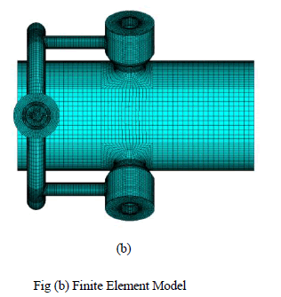
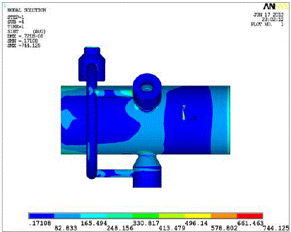
| Fig-2 gives the snap shot of finite element model (FEA) generated in ANSYS. This FEA model is common for both thermal and structural analysis. Good quality hexahedral elements are used in building the FEA model with warning element count less than 0.05% as per ANSYS software quality criteria [4]. To analyze the components thermal behavior under plant load condition, a non-linear steady state thermal analysis has been performed. |
 |
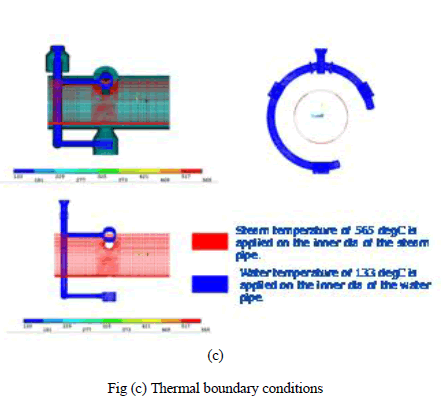
| Heat Transfer coefficients were calculated based on correlations available in literature mentioned in reference [6, 7] for the operating conditions of steam & water. Heat transfer coefficient for each surface is required for running thermal simulation. Fig-3 shows the thermal boundary conditions (cold start condition) used in simulation. Under cold start condition, the initial temperature of the component is assumed as 25degC. For the zone map shown in fig-3, heat transfer coefficients are calculated. Steam pipe is of superheated steam at 565 deg C & 133bar and feed water pipes are at 133 deg C and 213 bar are of water at 177degC & 163bar. |
 |
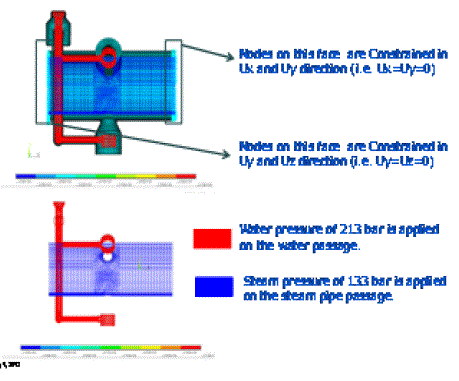
| In structural analysis, entire attemperator line is not modeled. Rather 0.5m upstream and 0.5m downstream of the main steam pipe was taken in structural analysis. FEA model is constrained at upstream and downstream as shown in fig-4 to simulate the field conditions. |
 |
| Fig (d) Structural constraints |
IV. RESULTS AND DISCUSSION |
| Fig-5 shows the temperature distribution in the attemperator assembly at a given load condition mentioned in previous section. Thermal simulation results show that very high temperature gradient exists between main steam pipe and nozzle connection. Steam pipe is at a higher temperature (steam temperature), spray nozzle & feed water pipes are at water (lower) temperature and the transition of high temperature to low temp is happening in very short distance (weld region of main steam pipe and nozzle holder). |
 |
| Fig (e) Temperature distribution in attemperator assembly |
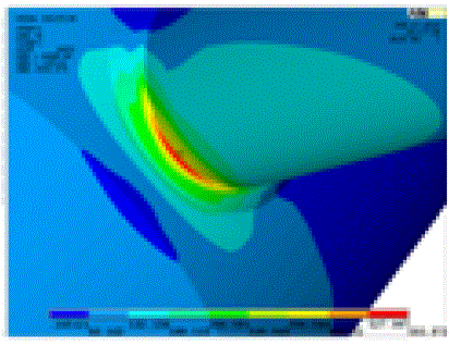
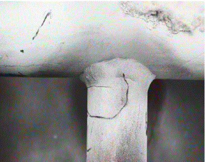
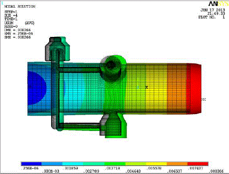
| Structural analysis is performed based on temperature distribution shown in Fig-5 and mechanical loads and constraints mentioned in previous section. Fig-6 shows the contour of von-misses stress plot from ANSYS in the overall attemperator assembly. Fig-7 shows zoomed picture of stress contour in the weld region of water leg and water connection. This is the region where cracks were appearing in the field. A high stress of 744.125 Mpa is observed at this location. Fig-8 shows the snap shot of location of crack in the field. |
 |
| (f) |
 |
| (g) |
| Fig (f) Maximum stress intensity (g) Zoom-in view of figure (f) |
| Structural results show that stress concentration is appearing in the weld region between water leg and water connection. This was an unexpected result as temperature gradient is negligible in this region as shown in Fig-5 from thermal simulation results. This result also suggested that disproportionate thermal expansion in the water legs is the cause for high stress. Fig-9 shows deformation plot (including thermal expansion) in the attemperator assembly. |
 |
 |
| Fig (h) Crack in the field condition Fig (i)Deformation contour (in meter) |
| As expected, deformation plot showed that water legs have different deformation in the pipe direction. Differential thermal expansion in the pipe direction is causing bending stress in the weak region (weld between water leg and water connection). Currently steady state condition is simulated in the study. If transient effect is considered in the simulation, bending stress will increase further. Water leg length plays a significant role in minimizing bending stress produced as it is controlling the flexibility in the assembly. A sensitivity study is performed to understand it (steady state analysis). In the study, water leg length is changed and bending stress is calculated in each case. Base on the sensitivity study, a correlation is proposed for bending stress based on the water leg length as shown in Fig-7. It is evident from the correlation that bending stress is non-linearly as water leg length is reducing. |
| y = 4.8381x2 - 199.25x + 2437.6 (1) |
| Where, Y is the stress induced in MPa |
| X is the stem (water leg) length in mm |
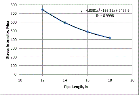 |
| Fig (j) Stress (MPa) versus increased in stem length (in ) |
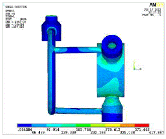
| As a solution to the current field issue, water leg length of 18in which was 6in more in length compared to base line design. Fig-11 shows the long stem design of 18in water leg length. Thermal and structural analyses were performed for validating the results. Simulation results showed that bending stress was reduced by 44% at “cracked” location to 417.8MPa. For simulation results for long stem design, ref Fig-11 & 12 |
 |
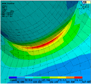 |
| Fig (k) Maximum stress intensity Fig (l) Zoom-in view of von- mises contour |
VI. CONCLUSIONS |
| Thermal gradient is not directly responsible for cracks in the weld region. Bending stress produced due to thermal expansion/contraction is causing cracks. To eliminate cracks at the weld between water leg and water connection pipe, bending stress should reduce significantly. As shown in correlation [Eqn-2], water leg length must be increased for reduction in bending stress. Increase in water leg length increases “flexibility” in the attemperator assembly and leads to lower bending stress for the same load conditions. |
References |
|