International Journal of Innovative Research in Science, Engineering and Technology
ISSN ONLINE(2319-8753)PRINT(2347-6710)
ISSN ONLINE(2319-8753)PRINT(2347-6710)
| Swagat PatiApplications 1, Abinash Panda1, Sumit Sen Behera1 Department of Electrical Engineering, Siksha „O? Anusandhan University, Bhubaneswar, Odisha, India. |
| Related article at Pubmed, Scholar Google |
Visit for more related articles at International Journal of Innovative Research in Science, Engineering and Technology
In the recent days DFIG has been the most favorite option for wind power harnessing. Most research in the area of wind power generation system is based upon the control and performance improvement of the DFIG as a generator in variable speed wind energy systems. The slow and complex dynamics of the DFIG makes it a challenging task for high performance control structures. In this paper a DFIG based variable speed wind energy system is considered. A hysteresis current controller based stator flux oriented vector control scheme is implemented for the high performance control of the system. The control scheme relies upon two conventional PI controllers and three hysteresis band current controllers for the control purpose. The system is evaluated under different types of disturbances and the results are produced in this paper.
Keywords |
| Doubly-fed induction generator, Rotorside vector control, P- I controller. |
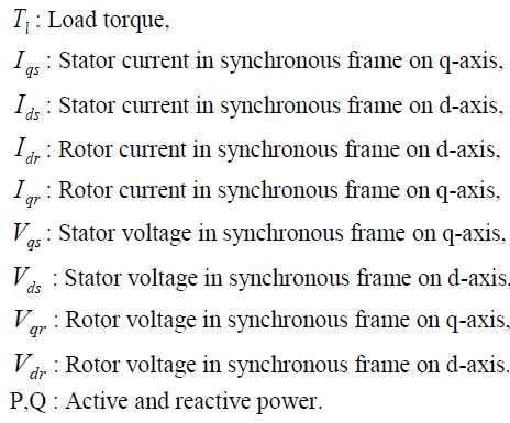
NOMENCLATURE |
| P: Number poles of induction motor, |
 |
 |
INTRODUCTION |
| Induction machines have served well as generators in wind energy conversion system for a long period of time. Initially for fixed speed wind energy conversion systems squirrel cage induction machines were employed as power generator for their rugged design, maintenance free performance and greater efficiency. But with the development of variable speed wind energy conversion systems the choice of generator has shifted towards doubly fed induction machines. Doubly fed induction machines inherit all the advantages of a cage induction generator but the fact due to which they are more popular are that the stator of the DFIG is connected directly to the grid and it supplies power from the stator side at grid voltage and frequency[1][2]. Other than that the control is done from the rotor side. So the power converters used for DFIG control are of less power rating, which reduces the cost as well as the switching losses, which results in enhanced efficiency. Further the doubly fed induction machines can work in the generation mode both above and below synchronous speed [2].these advantages of DFIG sets an efficient and flexible platform for variable speed wind power generation. The major drawback of DFIG as a generator is slow response due to coupling of active and reactive power. This drawback can also be compensated by use of advance control strategies. Different type of control schemes have been proposed for the control of DFIGs. Among them direct torque control [2], direct power control [2] and vector control [9] strategies are the most frequently used control schemes. Direct torque control is a simple strategy but as it involves hysteresis band flux and torque controllers it suffers from greater torque ripples [11]. But vector control scheme on the other hand is decoupled control scheme which enables independent control of active and reactive power [4]. So the control becomes faster and precise. In this paper a DFIG based wind energy conversion system is studied. The major highlight remains on the control of rotor side convertor for the improvement of the transient and steady state performance of DFIG. In this work a stator flux oriented vector control strategy is implemented for the control of the rotor side by directional converter. The vector control process employs conventional PI controllers. The control strategy generates PWM switching signals through a current regulated PWM scheme, which consists of three hysteresis band controllers. The whole system is modelled and simulated in MATLAB/Simulink environment and the results are analyzed. |
DOUBLY FED INDUCTION GENERATOR MODELLING |
| Modelling of an induction machine in three phase reference is quiet a complex and tedious task. So to reduce the complexity the machine model is converted from 3 phase to 2 phase synchronously rotating reference frame [1]. The modified voltage equations for the rotor and stator on the synchronously rotating reference frame are as follows:- |
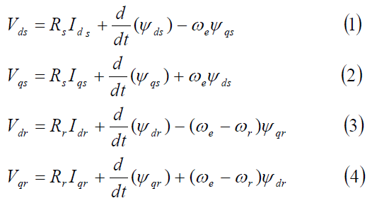 |
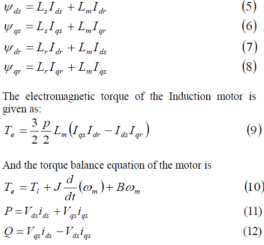
| The flux linkages in synchronous rotating frame can be expressed as |
 |
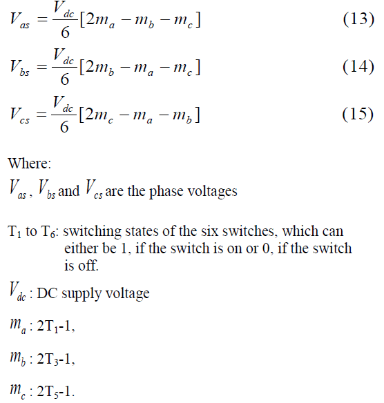
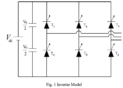
INVERTER MODEL |
| The PWM bidirectional inverter can supply power at variable frequency and voltage as well.[6] The equations required for modelling of the VSI can be written as follows |
 |
 |
CONTROL STRUCTRUE |
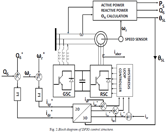
| This DFIG control scheme is a rotor side control scheme where the reactive power is controlled by the direct current axis loop and the active power is controlled by the quadrature current axis loop. In the active power control loop the speed is compared with reference speed and the error is fed to a conventional PI controller to generate the reference quadrature axis current. Similarly the stator side reactive power is calculated and is compared with the reference of reactive power and the error is fed to another PI controller to generate the reference direct axis current. Then both the direct and quadrature axis reference currents are converted to 2 phase deqe to 3 phase ac quantities the PWM generation structure considered here is current regulated PWM (CRPWM) [6]. In this PWM structure the 3 phase reference current are compared with the 3 phase actual current and the errors fed to 3 hysteresis band controllers. The band widths of the controllers are set at 5% of the rated current values. The hysteresis controller output gives the PWM switching pulses for the rotor side bidirectional converter control. The whole control scheme can be referred from Fig. (2). |
PI CONTROLLER DESIGN |
| The output signal of a PI controller can be obtained by the equation given below |
| Where „eâÃâ¬ÃŸ is the error signal. KP, KI the proportional gain and integral gain respectively. Here the gain values of the controller are tuned manually to obtain a near optimum result. |
 |
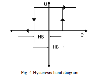
HYSTERESIS BAND CONTROL DESIGN |
| The hysteresis band controller is described by the following equation |
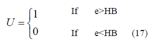 |
| Where „HBâÃâ¬ÃŸ is the hysteresis band width, which is taken to be 0.1 Amp. in this paper. The working of hysteresis band can be seen from the Fig. 4. When the error exceeds the value HB then the output of the controller becomes „1âÃâ¬ÃŸ and when the value of error less than –HB the output becomes „-1âÃâ¬ÃŸ |
 |
SIMULATION RESULT |
| The DFIG control structure was modelled and simulated in Matlab Simulink. The simulation results obtained by the steps given below |
| Step change in reference speed command. |
| Step change in load torque. |
| Step change in rotor reactive power |
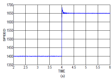
| A. Step change in speed command:- |
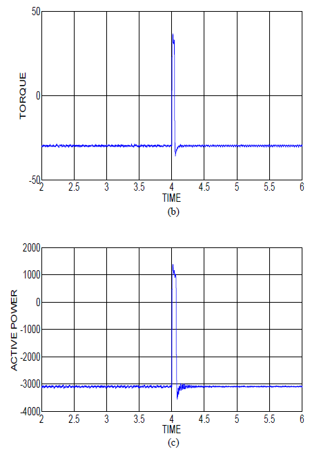
| In this section the system is subjected to a step change in reference speed at time 4 second. The reference speed command is changed from1400RPM to 1650 RPM on the response of the system are given below. Fig. 5(a) shows how the speed tracks reference speed. The overshoot for the speed response is 1.5% and the settling time is 0.15 second. Fig.5 (b) shows the electromagnetic torque response. It can be seen that there is a large overshoot in torque during the step change and again at the steady state it attains its previous value. Fig.5 (c) shows the active power response. As the speed increases the torque remaining constant the active power increases from -3100 to 1376 for a transient period of 0.15 second. |
 |
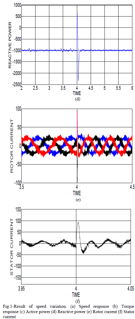
| The reactive power remains unaltered at its reference value of 1000 VAR excepting the transient time which can be seen from Fig.5 (d) Fig.5 (e) and 5(f) shows the rotor and stator currents respectively. It can be clearly noticed from Fig.5 (e) that the rotor current frequency increases as the speed increases from 1400 RPM to 1650 RPM because the relative speed has increased from 100 RPM to 150 RPM. But although the speed has changed the stator side frequency remains same as the supply frequency as shown in the Fig.5 (f). |
 |
 |
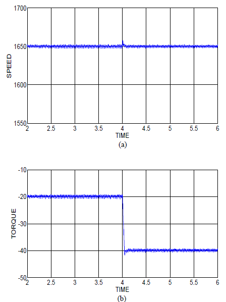
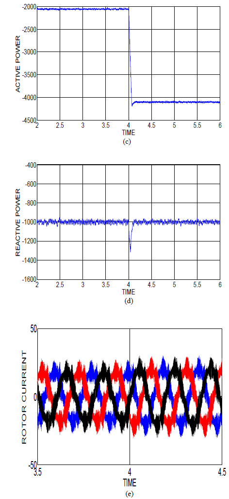
| B. Step change in torque |
| In this section the speed is kept constant 1650 rpm reactive power command is kept constant at -1000 var and a step variation in turbine torque given at 4sec. the turbine torque increases form -20NM to -40NM in the electromagnetic torque response can be seen from Fig.6 (b) the speed remains constant at the reference value which is evident form Fig.6 (a) and the reactive power response is given in Fig.6(d) where it can be seen that the reactive power remains constant at -100 var excepting the transient time. Fig.6 (e) and (f) show the three phase currents of rotor and stator respectively. From both the figures it is evident that as the torque increases the current magnitude of stator as well as rotor increases, but there frequency remains constant due to the reason that the speed of the machine remains constant |
 |
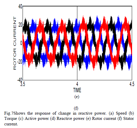
| C. Step change in reactive power:- |
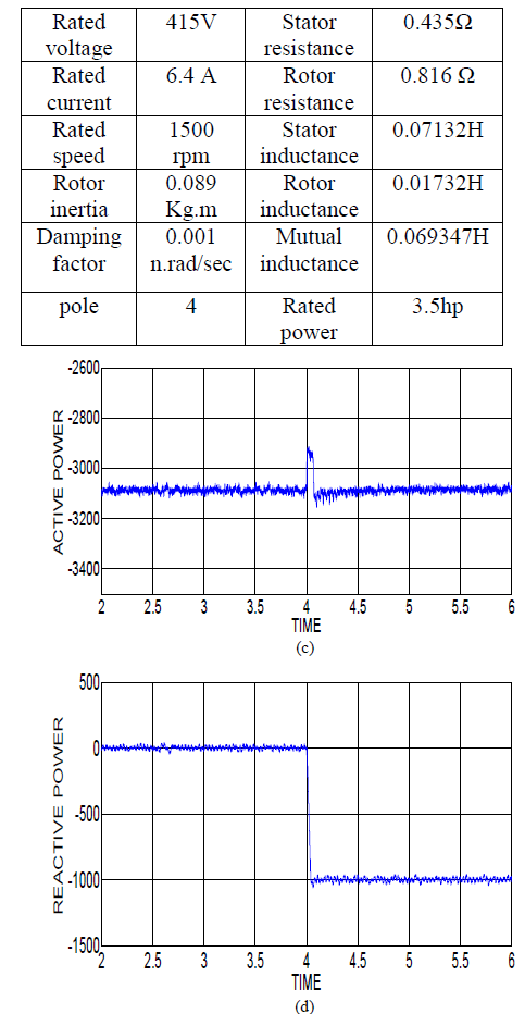
| In this part of the simulation the speed and torque are kept constant at 1650rpm and -30NM respectively and a step change in the reactive power command is given at 4 second. The reactive power command is varied from 0 to 1000var at 4 sec and the results are presented below. Space as can be seen from Fig.7 (a) and (b) the speed and torque are being constant at their reference values the active power response is given in Fig.7 (c) where it can be seen that the active power remains fairly constant the reactive power response in Fig.7 (d) shows that the reactive power fairly tracks its reference value Fig.7 (e) and (f) shows the three phase current wave forms of rotor and stator respectively. As there is no change in speed the frequency at stator and rotor side remain constant. |
 |
 |
 |
 |
CONCLUSION |
| The stator flux oriented vector control scheme for the control of rotor side converter of a DFIG based wind power conversion system is successfully modelled and simulated in this work. The hysteresis band based current control scheme proves satisfactory for the control process. But the use of hysteresis band controller increases the band width of switching frequency which makes the design of filter more expensive. But the hysteresis band based current control scheme is more robust and faster than the synchronous current control schemes which makes the proposed scheme to be more reliable and better suited for wind energy application. |