ISSN ONLINE(2319-8753)PRINT(2347-6710)
ISSN ONLINE(2319-8753)PRINT(2347-6710)
Pranav Mahamuni 1, Pratik Bhansali 1, Akhilesh Kulkarni 1, Yash Parikh 2
|
| Related article at Pubmed, Scholar Google |
Visit for more related articles at International Journal of Innovative Research in Science, Engineering and Technology
Payload Fairing protects a spacecraft from temperature heating during the initial launch stages in region of dense atmosphere. Shock waves are formed in the transonic region of flow, which makes the faring the most unstable in this phase. This paper aims at studying and reducing the unsteady pressure levels and hence also the aero acoustic loading in the transonic region i.e. Mach number 0.7 to 1.2. The separation area as well as the shock strength must be reduced. For this reason, flow stimulation to study pressure distribution, shock strength and separation was carried out. The Mach number at which the minimum flow separation as well as the shock strength is the most preferable one.
Keywords |
| Payload fairing, Spacecraft, Transonic region, Mach number, Flow simulation. |
INTRODUCTION |
| A spacecraft is subject to various factors, including dynamic pressure and aerodynamic heating due to the atmosphere during its launch. To protect the payload during the pre-launch operations and during the initial flight stages, a nose cone, commonly called Payload Fairing (PLF) is used in the forward most section of the launch vehicle. It serves and additional purpose of providing a clean room environment for the precision instruments. It encloses both the payload and the upper stage of the rocket in some cases [1]. Once the spacecraft transcends the dense atmosphere, it is jettisoned, thus exposing the payload. The standard shape of PLF is the cone-cylinder combination. However, specialized configurations are used as well. T. Ochinero and T. Deiters developed asymmetric PLF designs [2]. E. Dimitri and V. Bigeralla used viscid and in the viscid flow analysis for pressure distribution over blunt configurations [3]. Clamshell fairing is a type of fairing which splits in two halves during jettisoning. |
 |
| Fig. 1 is a representation of the jettisoning of the Clamshell type PLF. The fairing splits into two while separating from the spacecraft. The strength of shock in this transition can cause instability and may cause separation of flow. Thus, it is important to reduce the shock strength. |
II. CASE STUDY |
| Flow analysis is important in the aerodynamic analysis of PLF. This paper presents a detailed review of the work on an aerodynamic study of PLF by Angelin et al. [4]. |
| This study covers the CFD analysis of the flow in the transonic region (Mach no 0.7 to 1.2). Validation was done by carrying out the grid convergence study. For accurate capturing of the flow field, fine grid was generated over the heat shield surface. NS turbulent solver was used for the simulation. |
| PLF configuration must be such that it accommodates maximum possible payload and maintains aerodynamic shape to keep the launch vehicle loads much below the design load [5]. |
 |
| Fig. 2 shows a simplified 2 dimensional view of the PLF configuration used for this study. It consists mainly of spherical nose cap, nose cone, cylindrical portion and boat tail [4]. |
| The results of the study done for transonic Mach numbers are analysed below. |
| The comparison of parameters using various Mach numbers from 0.7 to 1.2 in the steps of 0.05 was studied. The obtained results are as follows. |
| 1. Pressure Distribution and Shock Location |
| There is a discontinuity in the surface curvature at various junctions of the PLF. This discontinuity affects the pressure distribution. The Mach number at the approach to the nose cap is in the subsonic region. As the flow approaches the nose cap, stagnation point is formed. The velocity at this stagnation point is zero. After this point, the flow accelerates as it flows along the nose cone and eventually becomes subsonic till it reaches the nose cylinder junction. The flow attempts to regain free stream properties as it now flows along the cylinder. The approach Mach number is responsible for affecting the flow behaviour. Fig. 3 to 5 show the variation of pressure with the non-dimensional length “X/D” for Mach numbers 0.7 to 0.8, 0.85 to 1.0 and 1.05 to 1.2. |
 |
| The peak value of pressure is at the stagnation point. As the flow expands further, an obvious drop in pressure is observed. The flow first expands along the spherical nose cap region. There is a change in geometry at the nose cap junction and the pressure increases due to positive gradient. Further the pressure remains almost constant in the cone region or decreases slightly. |
 s s |
| There is a sudden expansion in the cone-cylinder region. Thus the pressure falls sharply at the junction. The pressure is regained after the junction and the pressure suddenly jumps, thus indicating an ultrasonic shock from Mach number 0.7 to 0.95. |
 |
| From Fig. 3, Fig. 4 and Fig. 5, it can be noted that as the Mach number increases, the location of the shock moves towards the boat tail region. In Fig. 6, it can be seen that shock wave moves downwards in Mach numbers 1.05 to 1.2. As the Mach number increases, the expansion of flow increases. |
 |
| Flow separation does not take place for low Mach numbers in the transonic regime and there is a short separation for Mach numbers in the range 0.85 to 0.9. It can be seen in Fig. 6 that flow separation does not take place when the Mach number is between 1.0 and 1.2. |
2. Separation Length |
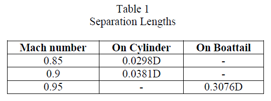
| As discussed above, there does not exist considerable flow separation in the low Mach number flow in the transonic regime and short distance separation takes place for Mach numbers around 0.9. So it can be noticed in table 1 that the flow separation length is longer as Mach number increases and the shockwave moves in boattail region at Mach number 0.95. |
 |
 |
III. CONCLUSION |
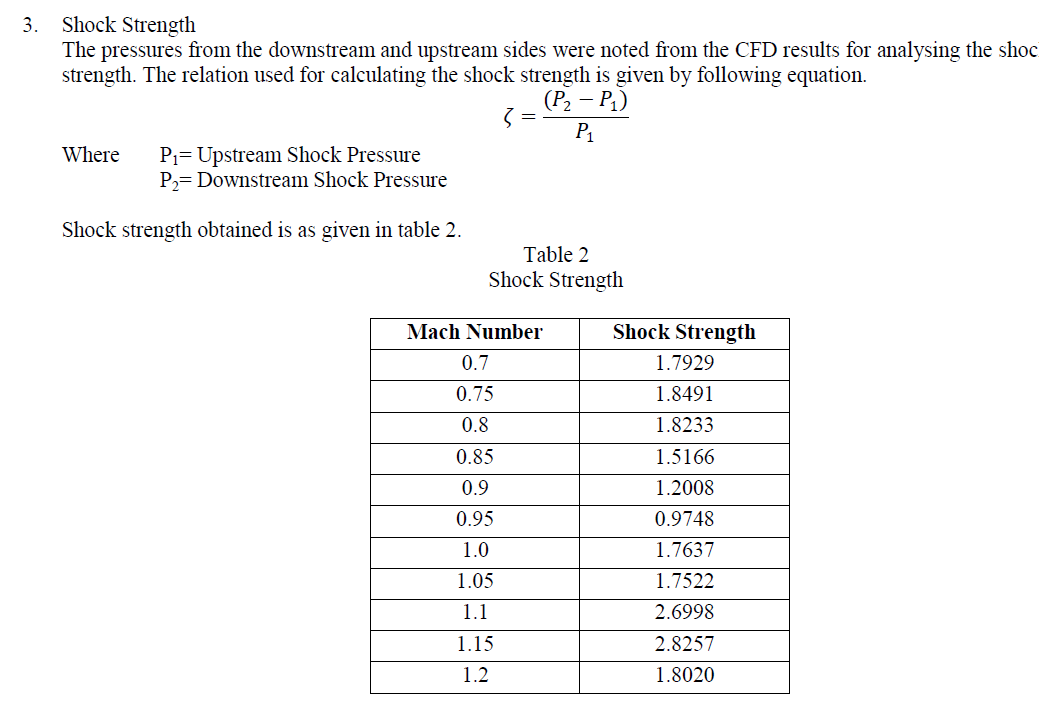
| From case study it is observed that as Mach number increases, the shock moves towards the aft body of the cylinder. For lower transonic Mach numbers, flow separation occurs and for higher Mach numbers in the transonic regime, shock is formed, but no shock induced separation occurs. Near the cone cylinder region, expansion waves are formed and they increase with the Mach number. It is also observed that as Mach number increases from 0.7 to 0.95, the shock strength reduces hence the shock waves strength also varies with the Mach number. This paper can be used as a reference for the design and modification of Payload Fairing Configuration. |
ACKNOWLEDGEMENT |
| The authors would like to present their sincere gratitude towards the Faculty of Mechanical Engineering in Sinhgad Institute of Technology and Science, Pune and Symbiosis Institute of Technology, Pune. |
References |
|