ISSN ONLINE(2319-8753)PRINT(2347-6710)
ISSN ONLINE(2319-8753)PRINT(2347-6710)
R.Deivanayaki, V.V.Rajasegharan, Dr.L.Premalatha
|
| Related article at Pubmed, Scholar Google |
Visit for more related articles at International Journal of Innovative Research in Science, Engineering and Technology
Super capacitors and batteries are extensively used energy storage devices that deliver an output voltage at the range of 12 to 70v DC. In contrast to super capacitors, batteries have vast scope of applications. A key obstacle in using batteries is that the charger cannot be connected directly to the grid. The focus of this paper is the comparison between various dc-to-dc converters employing soft switching techniques using fixed frequency transitions with zero voltage switching (ZVS). Among the various soft switching configurations, the LCL Series Resonant dc-todc converter with capacitive output filter is proposed. The implementation of the LCL Series Resonant dc-to-dc converter can be improvised by the addition of a ZVT Boost converter at the input side (i.e. ZVT Boost converter followed by the LCL Series Resonant converter) and hence the ZVS can be maintained for wide variations in input voltage and load current
Keywords |
| ZVT Boost converter, DC-to-DC converters, Resonant converters, battery charger. |
INTRODUCTION |
| Recently, the usage of the electric vehicles has increased across the world. The brainstorming would make it possible for a super capacitor pack to replace the battery pack with no loss in performance. We could still get the 300 mile range. However, the recharge would only take seconds to achieve. Further, super \capacitors do not degrade with use. The EVs can compete toe to toe with fueled vehicles. We can take them on long trips and only spend seconds to recharge and continue the journey. Now we no longer worry about battery life because super capacitors do not degrade. Now, finally the EV can replace the fueled dinosaur vehicle technology. Fuel independence becomes a reality. |
| The steady flow of power between the system elements that is the available energy from different sources is coupled to a low voltage dc bus. A direct connection of dc bus to the battery charger is not suitable because it to control the power flow between the input source and the charger. Therefore, a power conditioning or connecting system, usually a dc–dc converter, is required to couple the battery charger to the system bus. |
II.POSSIBLE CONVERTER CONFIGURATIONS |
| For the battery charger application, the High frequency transformer isolated or High Frequency (HF) switching dc-to-dc converters are suitable. The converter switches which have been used are super junction MOSFET’s with reduced forward resistance in the conduction mode and improved dynamic characteristics in the switching transients. Resonant converters possess several desirable features like zero voltage switching, zero current switching, high frequency operation, high efficiency, small size and low electromagnetic interference. Thus to obtain high efficiency and high switching frequency with reduced size, cost, losses and electromagnetic problems, the soft switching techniques can be used here. Soft switching refers to resonant tanks in the converters to create oscillatory (usually sinusoidal) voltage or current waveforms so that zero voltage switching (ZVS) or zero current switching (ZCS) conditions can be created for the power switches. The reduction of switching loss and the improvement of power switches allow the switching frequency of the resonant converters to reach hundreds of Kilo-Hertz (typically 100KHZ to 500KHZ). This can be explained through a block diagram as given below , Fig1.1. |
 |
| Soft switching converters can exhibit reduced switching loss, at the expense of increased conduction loss. Obtaining zero-voltage or zero-current switching requires that the resonant elements have large ripple; often, these elements are operated in a manner similar to the discontinuous conduction modes of the series or parallel resonant converters. As in other resonant schemes, the objectives of designing such converter are: 1) to obtain smaller transformer and low-pass filter elements via increase of the switching frequency, and/or 2) to reduce the witching loss induced by component non idealities such as diode stored charge, semiconductor device capacitances, and transformer leakage inductances and winding capacitance. |
| The possible HF transformer isolated soft switching converter configurations are i) Current fed resonant converters, ii) Voltage fed resonant converters, iii)Fixed frequency resonant transition zero voltage switching (ZVS) pulse width modulation (PWM) bridge converters. Among the above three configurations, the current fed resonant converters will reduce the efficiency as the HF switches may require a high input voltage ratings. The voltage fed resonant converters can provide operation either in variable frequency or fixed frequency operation mode. The operation in variable frequency mode has a disadvantage when there is a wide variation in switching frequency makes the design of filters and control circuit complex. Hence fixed frequency operation is preferred in this paper. |
| From all the above considerations, we have left with three major configurations for battery charging application. There are other configurations with fixed frequency mode[1], they are a)fixed frequency series resonant converter b)fixed frequency parallel resonant converter and c)fixed frequency series-parallel resonant converter. Thus the considered converter configurations are as follows: |
| i) Phase-shifted ZVS PWM full bridge converter |
| ii) LCL Series Resonant converter (SRC) with an inductive output filter [3] |
| iii) LCL Series Resonant converter (SRC) with a capacitive output filter[4],[5] |
| The merits of SRC includes better load efficiency and inherent DC blocking of the isolation transformer due to the series capacitor in the resonant network. However the load regulation is poor and output voltage regulation at no load is not possible by switching frequency variations. |
A. Phase-shifted ZVS PWM full bridge converter |
| This converter has reduced peak current stresses compared to a resonant converter[7,8,10]. The ZVS for the switches is realized by using the leakage inductance of the transformer (together with an external inductor) and the output capacitance of the switch. The theoretical switching circuit for phase-shifted ZVS PWM full bridge converter is shown in fig.1.2 . |
 |
B. LCL Series Resonant converter with an inductive filter |
| This converter also operates in lagging PF mode for a very wide change in load and the supply voltage variations, thus facilitates ZVS for all the primary switches. The peak current through the switches decreases with load current and is approximately clamped to the load current. The theoretical switching circuit for LCL Series Resonant converter with an inductive filter is provided as follows in Fig.1.3. |
 |
C. LCL Series Resonant converter with Capacitive filter |
| This converter operates in lagging power factor (PF) mode for a very wide change in load and the supply voltage variations, thus ensuring ZVS for all the primary switches. The peak current through the switches decreases with load current. The switching circuit of LCL SRC Resonant converter is shown in fig1.4 |
 |
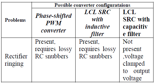
| In the case of first two configurations, a snubber circuit is needed across the output rectifier to clamp the voltage ringing due to diode junction capacitance with the leakage inductance of the transformer. |
| From the above circuits, it is concluded that the LCL SRC with a capacitive filter is found to be suitable for the proposed application. |
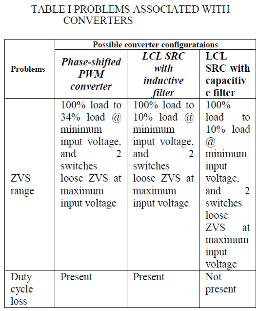
| The problems associated with the various converters are provided in Table I. |
| Some of the advantages of the chosen LCL SRC with capacitive filter over other configurations are as follows: |
| i) There is no duty cycle loss. |
| ii) This configuration doesn’t have any ringing problem. |
| iii) The duty cycle variation required is narrow for a wide range in power control . |
| iv) The value of the resonance inductance is the highest and it is difficult to realize low values required with high currents, building a practical converter is more difficult for the other two converters. |
| v) This scheme has a wide ZVS range for the MOSFETs. This scheme has a very good part efficiency as the current in tank circuit reduces with load current. |
 |
 |
III EVALUATION OF LCL SRC WITH CAPACITIVE FILTER’S PERFORMANCE |
| The performance analysis of LCL SRC with capacitive filter is achieved using the operating conditions as follows: |
| Vin,min = 40V for different load conditions with output voltage of Vo = 60V. At various operating and load conditions the theoretical approach can be obtained using approximate analysis. The converter is simulated using the POWERSIM program for the same operating conditions. The converter can also be simulated using SPICE program as well. The simulation results were provided as follows: The provided simulation is for the selected converter which is suitable for the required battery charging application. The waveforms are also provided. The waveforms are obtained for the above mentioned operating conditions, the gate triggering pulse waveform for switches S1 – S4 , terminal voltage Vab , resonant inductor current waveform are provided. |
| To achieve higher efficiency with reduced losses and also to maintain Zero voltage switching for all the switches during operation. Thus this approach provides ZVS for all the switches and thereby also simplifies the design of resonant components (Lr and Cs) design . |
 |
 |
IV DESIGN EQUATIONS |
| For LCL SRC with capacitive output filter |
 |
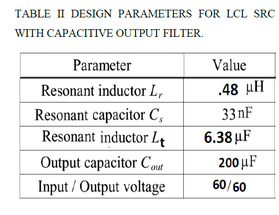 |
V IMPROVISED APPROACH |
| From the simulation we have the LCL SRC with capacitive filter has better performance and requires a small Lr which is very difficult to realize in practice and hence the input voltage is boosted using a ZVT BOOST converter to the SRC with a capacitive filter . The above mentioned approach is depicted using a block diagram in fig.1.8 and as a switching circuit in fig1.9 as follows. |
 |
VI. CONCLUSION |
| Thus this paper provides a comparison of various High Frequency transformer isolated, soft-switched, dc-to-dc converters. The three major configurations designed and compared are as follows: 1) LCL SRC with capacitive output filter; 2) LCL SRC with inductive output filter; and 3) phase-shifted ZVS PWM full-bridge converter. It has been shown that LCL SRC with capacitive output filter has the desirable features for the present application. It has been shown that none of the converters maintain ZVS for maximum input voltage. However, it is shown that LCL-type SRC with capacitive output filter is the only converter that maintains soft-switching for complete load range at the minimum input voltage while overcoming the drawbacks of inductive output filter. But the converter requires low value of resonant inductor Lr for low input voltage design. Therefore, it is better to boost the input voltage and then use the LCL SRC with capacitive output filter as a second stage. When this converter is operated with almost fixed input voltage, duty cycle variation required is the least among all the three converters while operating with ZVS for the complete variations in input voltage and load. |
| Therefore, we have investigated the performance of a ZVT boost converter followed by the LCL SRC with capacitive output filter. It was shown experimentally that the two-stage Approach obtained ZVS for all the switches over the complete operating range and also simplified the design of resonant converter. |
VII. FUTURE WORK |
| The proposed circuit can be designed for various operating conditions with different parameters. The simulation work canalso be carried out using MATLAB or PSPICE software. |
References |
|