International Journal of Innovative Research in Science, Engineering and Technology
ISSN ONLINE(2319-8753)PRINT(2347-6710)
ISSN ONLINE(2319-8753)PRINT(2347-6710)
Mohd Omer Farooq1, Dr Mir Safiulla2
|
| Related article at Pubmed, Scholar Google |
Visit for more related articles at International Journal of Innovative Research in Science, Engineering and Technology
Canister is a cylindrical shaped container, one end of which is open, in which bird specimen or ice pellets are loaded and fired in ice-pellet launcher system. The canister is propelled through the length of the gun barrel by means of compressed air and is arrested by canister arrester. High speed stainless canister with uniform and variable wall thickness is designed and then manufactured by the process of metal spinning in a spinning machine. For the canister to collapse without cracking, it is heat treated by annealing process. The base portion of the canister is hardened and the open end is made soft for it to collapse in desired fashion. The deformation of canister depends upon its length, internal diameter, wall thickness, shape of back face, hardness and ductility of the material. The study of collapsible characteristics of the canister is done using ABAQUS/Explicit software. For this 3D CAD modelling is done using CATIA V5 software and finite element meshing is done using HYPERMESH software. Collapsible characteristics of the canister are observed for uniform and variable wall thickness canisters, at different velocities. The result of this dynamic simulation which deals with the collapsibility characteristics of canister will be compared, at few specific velocities, for a few specific canister geometries, with the results of tests to be conducted on actual metallic canisters, in the canister launcher, now operational at the college.
Keywords |
| Canister, Metal Spinning, ABAQUS, HYPERMESH, CATIA V5 |
INTRODUCTION |
| Canister is the most critical Dynamic component in a bird launcher, which accelerates the birds or ice- pellet from rest to the desired launch velocity within a few milliseconds, the performance of the canister ultimately decides the correct velocity orientation, target accuracy, pitch and yaw positions of the birds at the time of impact of the engine that the safety of the rest article, either the static parts or the rotating parts of the engine are not compromised due to the cracking, tearing and the consequent release of the metallic debris of the canister. It keeps the ice-pellet/bird specimen centralized and coaxial with the launch barrel and provides necessary damping for withstanding the shock of launch impact with the arrestor lip, prevents the bird the rubbing with the internal surface of the gun barrel. |
| The canister is also expected to fold over least partially in the circumferential direction and thus serve to seat the high pressure air at the end of the gun barrel and prevent compressed air from gushing out into the target area and introduce secondary damage and minimize obscure visibility of the target components and thus help in obtaining clear high speed photography / videography. |
| The canister is a thin walled cylinder with either a flat back surface or a dome-shaped semi-hemispherical back end with the front end being open, for inserting the sabot and the bird specimen. The thickness of the cylindrical body as well as that of the back end could either be uniform or variable. The wall thickness at the front end and the rear end of the canister, wall thickness over on the cylindrical body are controlled during the deep drawing process. The strength of this canister, to withstand the “impact test shock”, is imparted to the canister during the heat-treatment process. There are major impact test programs in the country which are aimed at studying the penetration mechanisms, containment capability of “armor” materials, and bird strike capability of aero engine components. Many gas and compressed-air launchers are operating at Gas Turbine Research Establishment (GTRE), National Aerospace Laboratories (NAL), and Defence Metallurgical Research laboratory (DMRL) and Terminal Ballistic Research Laboratories (TBRL). These facilities do use canister of various sizes and materials. These are Over designed to ensure safety of the system but backed up by data on canister behaviour most of them work based on “Trial &Error” basis, with the attendant risk. Almost all defence selected agencies such as NASA, university Laboratories university of Dayton research institute (UDRI). For example aero engine manufactures such as General Electrical, Partt-Whitnery of USA Rolls Royce, UK, Snecina and France. Use highly optimized steel titanium canister for their impact programs. These are backed up by very detailed studies on materials, forming process, heat treatment, thickness and shape control on the canister. |
| Ice-Pellet Launcher is a Test Facility that launches ice pellets to simulate ice impact on aircraft and aero-engines. When ice pellets and slabs hit the aircraft, which fly at high speeds, including near-sonic speeds, they cause huge damage on to the body of the aircraft. This will also cause extensive damage to aero-engine parts, endangering the flight safety. The damage profile due to ice and even bird hits needs to be extensively analysed through simulation effort. More importantly they need to be experimentally studied by launching ice pellets on to aircraft/aero-engine parts at appropriate speeds and directions. |
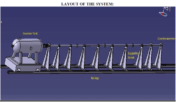
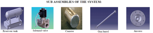
| Compressed air is used to launch the ice pellets/bird specimen or any other projectile in this facility. A metallic canister is used to hold these ice pellets and is surrounded by a layer of gelatine. A high pressure air-tank, with 1500 litre capacity 10 bar operating pressure rating, is filled with compressed air by a 10-kW air-compressor. This stored compressed air is made to suddenly gush out by opening an electronically operated solenoid valve or a sophisticated rupture disc. The expanding compressed air accelerates the ice-pellets housed in the metallic canister. The “fired” canister would accelerate throughout the length of the gun barrel/launcher tube connected to front of the air receiver, gets arrested at the Canister Arrester junction at the end of the gun barrel and ejects the ice pellets/bird specimen at the desired speed. Before the arresting action of the canister the velocity of the projectile inside the gun-barrel would be measured using a laser operated velocity measuring system. |
 |
 |
LITERATURE SURVEY |
| At the 1996 London Meeting of the International Bird Strike Committee, an illustrated working paper was presented that provided brief details of all fatalities and destroyed aircraft due to bird strikes during the period 1912 to 1995. The paper was felt to be useful in drawing attention to the scale of the problem especially when dealing with those who know little about the subject or who are newly appointed to decision-making positions. Since the original paper was published, information has come to light on a number of previously unknown accidents as well as information on recent accident. |
| I have now believed that the number of fatal accidents has risen to 42 killing 231 people. In addition, the total of air craft destroyed is now 80.These is as follows: |
| Airliners and Executive Jets -10 fatal accidents killing 164 and destroying 30 aircraft. |
| Aero planes 5,700kg and below -27 fatal accidents 58 and destroying 42 aircraft. |
| Helicopters -5 fatal accidents killing 9 people and destroying 8 helicopters. The paper provides briefs details on all above accidents together with some photographs. Analysis reveals that the threat (77% of accidents) to airliners and Executive Jets is engine ingestion, often due to flocks of gulls (Larus sp.). Aircraft of collision with birds of prey (Accipitriformes). These groups of aircraft mainly fly at heights where birds are most likely to be encountered. Some accidents are of pilots attempting to avoid birds. |
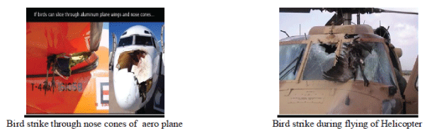
| Although not a major cause of fatalities, bird strikes are a serious safety and economics hazards. Bird strike accidents are events that can occur out –of –the –blue even at airports that may consider they have appropriate measures in place. The following figure shows Bird strike for plane & Helicopters: |
 |
PROBLEM DEFINITION AND FINITE ELEMENT MODEL DEVELOPMENT |
3.1 Problem definition: |
| Design, modelling of Canister and arrester for checking the collapsible characteristics are the main objective of the problem, which are as follows: |
| 1. Design of Canister |
| 2. Design of Arrester |
| 3. Overall modelling and meshing |
| 4. Analysis for Collapsibility |
3.2 Dimensional representation of the problem: |
 |
 |
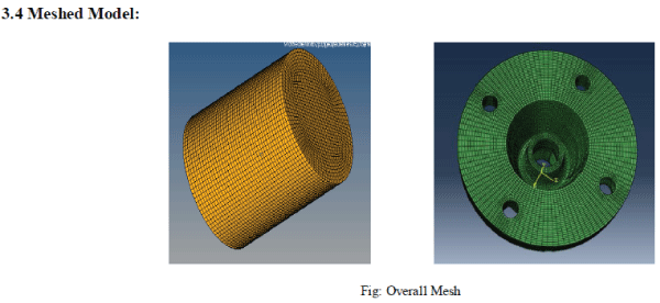 |
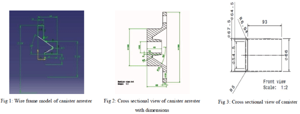
| The above figure shows the model of canister and die. Canister is a cylindrical cup like structure, with an inner part empty. The thickness of the canister wall is 0.5mm. Die is made of hard material so that it can withstand with high stresses. Total of 1314 elements with1722 nodes are used for maintaining connectivity. |
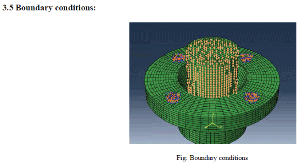 |
| The above Figure represents boundary conditions of the problem. Here bottom of die is fixed and the load on canister is applied with a uniform Velocity. So there is a need to check the collapsing condition of the problem. The problem is meshed with 8950 elements and 9131 nodes. |
3.6 Assumptions: |
| 1. Materials are assumed homogenous and isotropic up to yield point. |
| 2. Nonlinear domain is applied after yield stress. |
| 3. Contact elements are defined to obtain the solution, which employ iterative solvers for execution. |
| 4. All Finite element approximations are applied during solving. |
| 5. Bi linearity is assumed for nonlinear stress strain curve. |
RESULTS AND DISCUSSIONS |
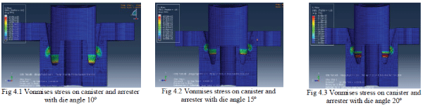
| The analysis is done on canister with different shapes and arrester with different angles . The analysis results are as follows. The following cases are analysed. |
| • Canister with flat bottom |
| • Canister with round bottom |
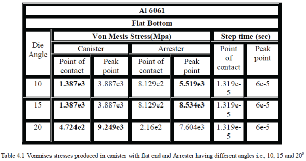
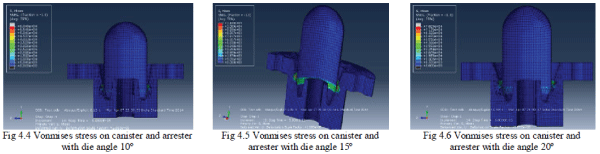
Case 1: Canister with flat bottom |
| The results are captured for stresses. The results are as follows. |
 |
 |
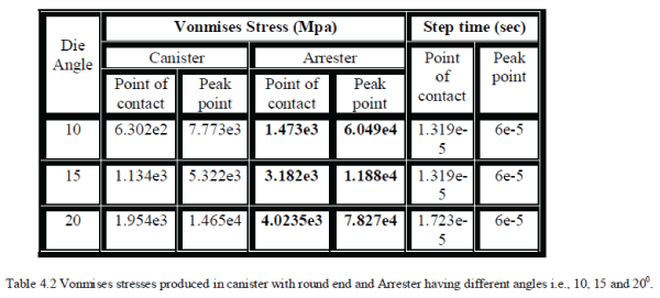
Case 2: Canister with Round bottom: |
| The results are captured for stresses. The results are as follows. |
 |
 |
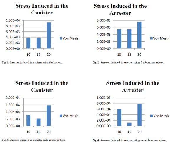
Bar Chart Showing the Comparison Between Different Die Angel of The Arrester: |
| Bar charts are used to compare between the results of same component of different parameter. Below is one such example which shows the comparison of arrester having different die angle with material, velocity and bottom shape of the canister keeping same. |
 |
CONCLUSION AND FEATURE SCOPE |
| Canister analysis has been carried out to check the structural stability and collapsibility. The canister and die along with the guide pipe are modelled and analysed for the collapsibility and bending of canister under different conditions. Due to axis symmetric nature, axis symmetric approach is applied. Shell element used for representation of the problem. The geometry is split to ease map meshing. Bottom is constrained and top nodes are constrained for uniform movement. From the analysis and by visualising the above bar charts it is evident that, when a 20 degree die angle Canister Arrester comes in contact with high speed canister. |
| • It experiences high stress. |
| • Maximum internal energy. |
| • Maximum kinetic energy. |
| • Maximum strain energy. |
| • Initially the canister is made to hit the arrester having 100 angle. The stresses induced are less and we are getting circular shape at the bottom end of the canister and small fold ability at front face. |
| • For 150 angles the stresses are slightly more and the folding is further increased. |
| • As per the reviews we will observe that the bent on the canister is perfect due to its ductility |
| • To get the more deformation in the variable thickness canister we have to reduce thickness at the bottom end of the canister from 1.5mm to 1mm. |
| • If arrester die radius is lesser, then more bending area is occurring. Then bending of canister in required shape and size will more accurate. |
| • As per the test results the damage to the die is very less, hence we can prefer for experiment |
Further Scope: |
| • Experiment should be carried on canister of varying thickness and simulation has to be done on same. |
| • Simulation can be carried out with non-linear properties of the material used to get accurate results. |
| • Actual work can be started based on the result obtained by the above simulation. |
| • Optimization of lip angel can be done for better results. |
| • Analysis should be carried out at different velocities. |
ACKNOWLEDGEMENT |
| I would like to express my sincere gratitude to my Parents, Young and dynamic Principal, Beloved Head of the Department and my energetic Guide, without their support and prayers it would not have been possible to complete this project. Last but not the least, I would like to extend my thanks to my friends who provided me with valuable suggestion to improve my project. |
References |
|