ISSN ONLINE(2319-8753)PRINT(2347-6710)
ISSN ONLINE(2319-8753)PRINT(2347-6710)
S.Ramila1, R.Maheswari2
|
| Related article at Pubmed, Scholar Google |
Visit for more related articles at International Journal of Innovative Research in Science, Engineering and Technology
Cloud Computing is a collection of servers hosted on the internet. User can request the cloud provider to get the services. One of the advantage of cloud storage is that the originality(integrity) of the data is maintained in the cloud. It can be achieved by various cryptographic techniques. This new data storage paradigm introduces some security challenges, which requires an auditing service to check the integrity of the data. In this paper, a various integrity checking schemes namely Provable Data Possession(PDP), Compact Proofs of Retrievability(CPOR), Dynamic Provable Data Possession(DPDP), Auditing and CPDP are analyzed and also conclude the best strategy to store the data.
Keywords |
| Solar-PV energy, Integrated SEPIC & KY converter, closed loop control, P&O approach, MPPT controller. |
INTRODUCTION |
| In this paper the performance of a low power stand-alone solar photovoltaic (PV) energy generating system with integrated SEPIC & KY converter is to be investigated. Due to the high system efficiency and the ability to operate with a wide variable input voltage, the proposed converter is an attractive design for alternative low dc voltage energy sources, such as solar photovoltaic modules and fuel cells. |
| Increasing energy demand and environmental issues over the fossil fuels have significantly developed the interest in green energy sources to replace fossil fuels. The photovoltaic (PV) power systems are gaining popularity more than other renewable sources because of their ease of installation, less maintenance and in isolated mode of power generation these are proven to be effective solution for feeding energy demand of rural areas. Due to environmental and economic benefits, PV is now widely utilized as a distributed energy resource in stand-alone modes .Power converters need to be incorporated in these systems because to supply consumer loads power quality needs to be considered and the solar power output varies with the environment and weather conditions. The application of renewable energy is increasing and consequently the use power converter for efficient utilization of these systems is also being analyzed. The total amount of solar insolation absorbed by the PV module is not converted into electricity but the major part of it contributes to increase the temperature of the panel, thus the efficiency of the system is a major issue A non isolated dc–dc converter with a high boost ratio would be advantageous for a two-stage PCS (Power Conditioning System) because it can be easily integrated with current PV systems while reducing the cost and maintaining a high system efficiency. Due to the different output voltages from the PV panel, it would be beneficial to have a system with a high efficiency over the entire PV voltage range to maximize the use of the PV during different operating conditions. |
| Another important function of the DC-DC converter for PV applications is being able to implement maximum power point tracking (MPPT). The ability to implement MPPT for an individual PV panel would ensure that a large cluster of PV could maintain maximum power output from each panel without interfering with the other panels in the system. The major consideration for the main power stage of the converter is being able to implement an accurate MPPT in that the input current ripple of the converter has to be low. |
| The main function of the MPPT controller is to obtain optimal operating point for the system and force it operate on this point with variations in temperature and solar radiation. For any PV system, the output power can be increased by two options; (a) increasing the incident solar radiation on the system, (b) tracking the maximum power point of the PV system. This strategy includes the control of duty cycle of the DC-DC converter. The system components are designed and simulated using Matllab/Simulink. The system performance evaluation under load disturbances, temperature variations, various insolation and duty cycles are carried out. Simulated results are presented to demonstrate the performance of the system in various atmospheric conditions. |
II. SYSTEM DETAILS AND DESIGN CONSIDERATIONS |
| Solar-PV cells produce electricity directly by converting the solar energy into electrical energy. The output voltage and current of the single PV cell is quite small to be used practically, thus these are used in seriesparallel combinations, called as PV array and modules to produce the significant level of voltage and current. The solar PV energy generation system is designed to feed an average load of 100 ohm, considering this load, the rating selected for the solar-PV panel is 100W. The specifications of the selected configuration are as follows, open circuit voltage (Voc) is 17.9V, voltage at maximum power point (Vmp) is 17.9V, short circuit current (Isc) is 4.95A and current at maximum power point (Imp) is 7.04A.Fig.1 shows the system composition with a MPPT controller. This system is composed of a solar-PV panel, an integrated SEPIC & KY converter, an energy storage system, to feed the loads. The variable dc voltage of the PV panel is converted to a constant dc voltage using the DC-DC converter. The output of PV array is boosted to 50V to provide a constant dc link for the battery charging.. [1] |
| The SEPI converter can achieve a high-voltage gain with the additional step-up ability of the isolated SEPIC converter and distributed voltage stress, while maintaining the advantages of the boost converter, such as a continuous input current and a clamped voltage stress on switch. |
| For designing the MPPT controller, the issues considered are its simplicity in the design and implementation of the controller and its efficiency in varying operating conditions. These methods force the system to operate on its optimal conditions with the variation in environment factors. The DC-DC converters and dc-ac converters are extensively explored to meet the requirements for renewable energy systems. Solar-PV system produces dc voltages and consumer appliances operate on the ac voltages, thus a VSI (voltage source inverter)can be utilized in this system as a dc-ac converter .[2]. |
 |
III. ANALYSIS OF INTEGRATED SEPIC & KY CONVERTER |
 |
| Or equal to that at its input, the output of the SEPIC is controlled by the duty cycle of the control switch. |
| A SEPIC is similar to a usual buck-boost converter, but has advantages of having non-inverted output, the output voltage is of the same polarity as the input voltage, the isolation between its input and output and true shutdown mode. SEPICs are useful in applications in which a battery voltage can be above and below that of the regulator's intended output. The SEPIC converter uses two inductors, one capacitor with a switch. The SEPIC exchanges the energy between the capacitors and inductors in order to convert from one voltage to another. The amount of energy exchanged is controlled by switch S1, which is a MOSFET. The MOSFETs offer much higher input impedance and lower voltage drop and do not require biasing resistors because MOSFET switching is controlled by differences in voltage rather than a current[1] |
| The main advantages of this converter are the continuous output current, smaller output voltage ripple, and lower semiconductors current stress compared with the conventional converter. The Basic topology of SEPIC converter is shown in Fig2 |
| It can be operated in two modes: |
| ïÃÆè Continuous Current mode |
| ïÃÆè Discontinuous Current mode |
Continuous Current Mode |
| A SEPIC is said to be in continuous-conduction mode ("continuous mode") if the current through the inductor L1 never falls to zero. During a SEPIC's steady-state operation, the average voltage across capacitor C1 (Vc) is equal to the input voltage (Vin). Because capacitor C1 blocks direct current (DC), the average current across it (Ic1) is zero, making inductor L2 the only source of load current. Therefore, the average current through inductor L2 (IL2) is the same as the average load current and hence independent of the input voltage. Average voltages can be written as |
| Vin = VL1 + Vc1 + VL2 (1) |
| Because the average voltage of VC1 is equal to Vin, VL1 = −VL2. For this reason, the two inductors can be wound on the same core. Since the voltages are the same in magnitude, their effects of the mutual inductance will be zero, assuming the polarity of the windings is correct. Also, since the voltages are the same in magnitude, the ripple currents from the two inductors will be equal in magnitude. The average currents can be summed as follows: |
| ID = IL1- IL2 (2) |
| When switch S1 is turned on, current IL1 increases and the current IL2 increases in the negative direction. (Mathematically, it decreases due to arrow direction). The energy to increase the current IL1 comes from the input source. Since S1 is a short while closed, and the instantaneous voltage VC1 is approximately VIN, the voltage VL2 is approximately −VIN. Therefore, the capacitor C1 supplies the energy to increase the magnitude of the current in IL2 and thus increase the energy stored in L2. |
| The capacitor CIN is required to reduce the effects of the parasitic inductance and internal resistance of the power supply. The boost/buck capabilities of the SEPIC are possible because of capacitor C1 and inductor L2. Inductor L1 and switch S1 create a standard boost converter, which generate a voltage (VS1) that is higher than VIN, whose magnitude is determined by the duty cycle of the switch S1. Since the average voltage across C1 is VIN, the output voltage (VO) is VS1 - VIN. If VS1 is less than double VIN, then the output voltage will be less than the input voltage. If VS1 is greater than double VIN, then the output voltage will be greater than the input voltage. |
B) KY converter: |
| KY converter named by the inventors Mr.KI .Hwu & Y.T. Yau. Has continuous in- put and output inductor currents, has a larger voltage conversion ratio. This converter is very suitable for low-ripple applications.This converter has the efficiency of 90%. This converter possesses fast load transient responses.[4] |
| It is a buck/ boost converter. It operates on low output ripples. It steps up the input voltage by varying the duty cycle. It operates on the non pulsating mode and produces the positive output voltage. |
| The detailed comparisons between the proposed buck–boost converter and the KY converter are described as follows. |
| 1) Both converters always operate in CCM. That is, the negative current can be allowed at light load, but the corresponding average current must be positive. |
| 2) Both converters have individual output inductors, thereby causing the output currents to be non pulsating. |
| 3) The proposed converter has one additional inductor and one additional capacitor so as to execute voltage bucking/ boosting as compared with the KY converter. Therefore, the proposed converter has the voltage conversion ratio of 2D, and hence possesses voltage bucking with the duty cycle locating between 0 and 0.5 and voltage boosting with the duty cycle locating between 0.5 and 1. On the other hand, the KY converter has the voltage conversion ratio of 1 +D, and hence only possesses voltage boosting with the duty cycle locating between 0 and 1. In addition, the maximum voltage conversion ratios for both are identical, equal to 2. |
| 4) Both these converters can operate bidirectional. The proposed converter works with the backward voltage conversion ratio of 0.5/(1−D), whereas the KY converter works with the backward voltage conversion ratio of 1/(2−D). |
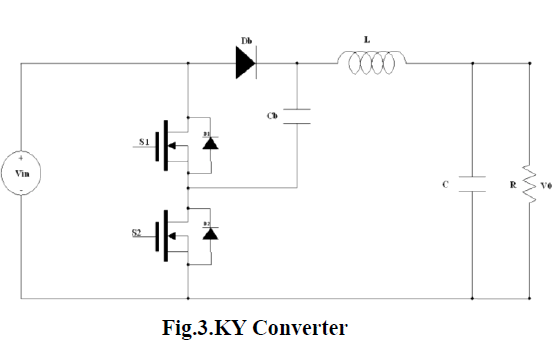 |
| It possesses non pulsating output current, thereby not only decreasing the current stress on the output capacitor but also reducing the output voltage ripple strategies. |
C) The integrated SEPIC & KY Converter |
| The integrated SEPIC & KY Converter with the dc supply driven by the solar photovoltaic cells is analyzed. This converter uses small value of inductors which yield high power density, and thus by improving the efficiency of the system. The output voltage is boosted up and also reduces the harmonic contents. It posses non pulsating output current, there by not only decreasing the current stress on the output capacitor but also reduces output voltage ripples. |
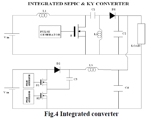 |
| This Converter uses smaller inductors which yielding high power density, thus improves the efficiency of the system. |
| The output voltage is boosted up and also reduces the harmonic contents. It posses non pulsating output current ,thereby not only decreasing the current stress on the output capacitor but also reduces output voltage ripples. |
| In this analysis the input from PV system is fed to the input of KY and SEPIC converters. The corresponding outputs are connected to the load and outputs are verified. Each converter is connected in parallel with the input and outputs are connected with the same load resistor. |
IV. SOLAR ENERGY CONVERSION WITH MPPT CONTROLLER |
| Solar energy is the most readily available source of energy. It is also the most important of the nonconventional sources of energy because it is non-polluting. Due to the rising costs and limited amount of nonrenewable energy sources, there is an increasing demand for the utilization of renewable energy sources such as photovoltaic(PV) modules. Integrating the power from the PV module into the existing power distribution infrastructure can be achieved through power conditioning systems (PCS). Performance of a PV-based system strongly depends upon the capability to determine an optimal operating point of the PV array at which the maximum power can be drawn for any given load. Therefore, maximum power point tracking (MPPT) of the PV cell is essential as far as the system efficiency is concerned. The dc–dc conversion stage of the PCS requires a high efficiency, high boost ratio dc–dc converter to increase the low dc input voltage from the PV panel to a higher dc voltage.[2] |
V. MODELING OF SOLAR-PV ARRAY |
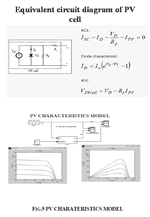
| The solar-PV array should be modeled taking concern of that the output characteristics of a solar-PV panel affects the MPPT controller and the power converters utilized in the system. A PV module comprises of several PV cells connected in either series or parallel combination .The solar insolation from the sun at the outer atmosphere is measured as, 1.373 kW/m2. Final incident sun light on the earth surface is considered of 1 kW/m2 after accounting forall the losses, at peak time with clear sky. The solar-PVcell being a non-linear device can be represented with a current source in parallel with diode as shown in Fig. 5. Single Diode model for solar cell equivalent circuit From Fig.3, the characteristics of the equivalent solar cell circuit can be expressed as, |
 |
| where Ipv is the output current from the PV array, Vpv is the output voltage of the PV array, Iph is the photo generated current of the PV cell, Ir is the reverse saturation current of the diode, q is the electronic charge, A is the ideality factor, K is the Boltzman constant, T is the operating temperature of the cell and Rs is the internal resistance of the cell. From the Eq.(1) the PV cell is modeled in Simulink. The effect of variation in solar radiation is obtained through the model and shown in Fig.6. From Fig.6 it is confirmed that the solar- PV output power is function of the input solar radiation. The operating curves under different levels of the radiation show maximum output power points. |
 |
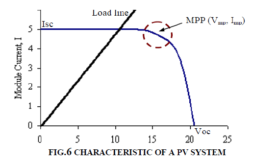 |
| The solar cell electrical characteristic (V-I) is nonlinear and varies with intensity of solar radiation (irradiation) and operating temperature. To use a MAXIMUM POWER POINT TRACKING (MPPT) algorithm to dynamically tune either control current or voltage by power electronic circuits (converter) |
 |
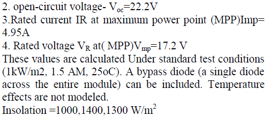
MODEL DESCRIPTION |
| 1. Short-circuit current- Isc =5.45A |
 |
VI. MPPT CONTROL SCHEME |
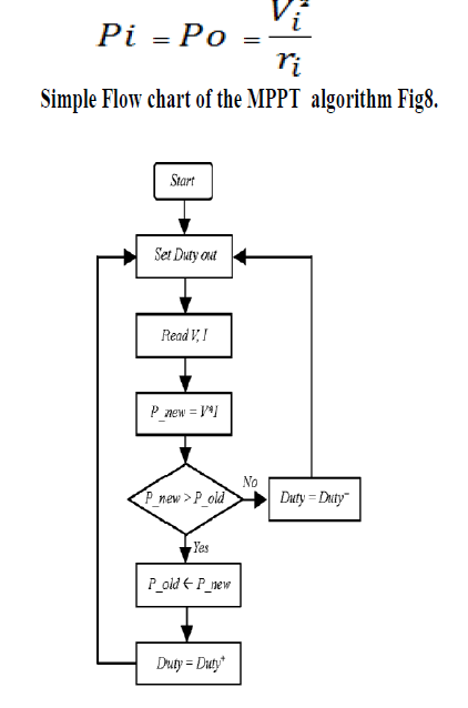
| Tracking the maximum power point (MPP) of a photovoltaic (PV) array is usually an essential part of a PV system. As such, many MPP tracking (MPPT) methods have been developed and implemented. The methods vary in complexity, sensors required, convergence speed, cost, range of effectiveness, implementation hardware, popularity, and in other respects. They range from the almost obvious (but not necessarily ineffective) to the most creative (not necessarily most effective). In fact, so many methods have been developed that it has become difficult to adequately determine which method, newly proposed or existing, is most appropriate for a given PV system. Given the large number of methods for MPPT, a survey of the methods would be very beneficial to researchers and practitioners in PV systems. The rate of change of input power with respect to input voltage and the resistance can be shown as follows.[2]. |
| The value of the current is directly controlled by the duty cycle of the control signal. The output power increases result in duty cycle control. This can be varied until the maximum voltage is reached |
 |
| Most techniques respond to changes in both irradiance and temperature, but some are specifically more useful if temperature is approximately constant. Most techniques would automatically respond to changes in the array due to aging, though some are open-loop and would require periodic fine-tuning. In our context, the array will typically be connected to a power converter that can vary the current coming from the PV array.[3] |
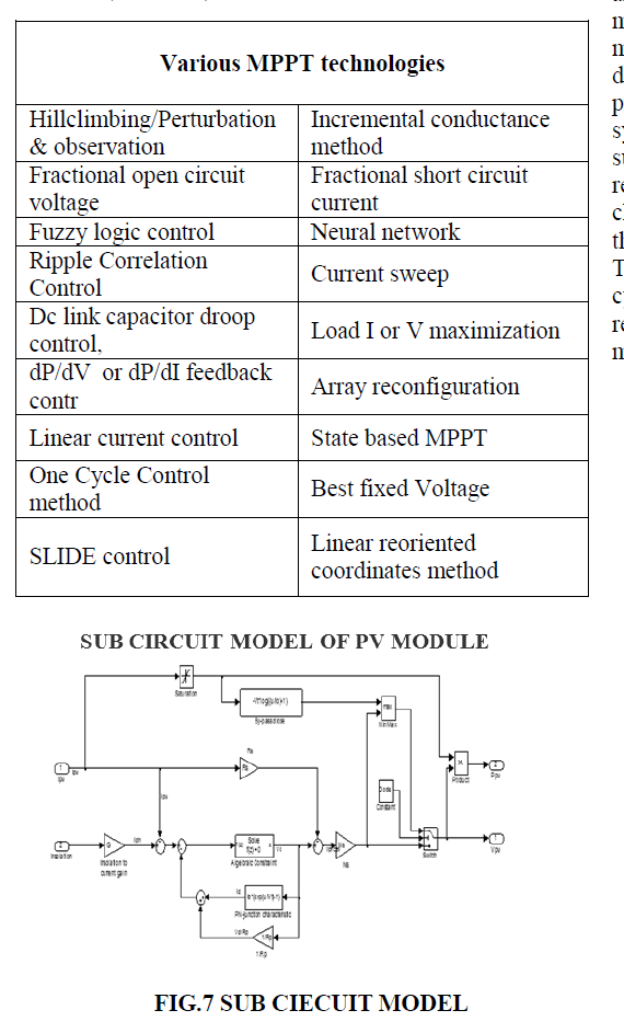
| Different MPPT techniques given will suit different applications [4]. For example, in space satellites and orbital stations that involve large amount of money, the costs and complexity of the MPP tracker are not as important as its performance and reliability. The tracker should be able to continuously track the true MPP in minimum amount of time and should not require periodic tuning. In this case, hill climbing/P&O, IncCond, and RCC are appropriate. Solar vehicles would mostly require fast convergence to the MPP. Fuzzy logic control, neural network, and RCC are good options in this case. Since the load in solar vehicles consists mainly of batteries, load current or voltage maximization should also be considered. The goal when using PV arrays in residential areas is to minimize the payback and to do so, it is essential to constantly and quickly track the MPP. Since partial shading (from trees and other buildings) can be an issue, the MPPT should be capable of bypassing multiple local maxima. Therefore, the two-stage Inc. Cond and the current sweep methods are suitable. Since a residential system might also include an inverter, the OCC MPPT can also be used.[3] |
| PV systems used for street lighting only consist in charging up batteries during the day. They do not necessarily need tight constraints; easy and cheap implementation might be more important, making fractional VOC or ISC viable |
HILL CLIMBING/P&O |
| The P&O method operates by periodically incrementing or decrementing the output terminal voltage of the PV cell and comparing the power obtained in the current cycle with the power of the previous one (performs dP/dV ). If the voltage varies and the power increases, the control system changes the operating point in that direction; otherwise, it changes the operating point in the opposite direction. it is shown that the algorithm also works when instantaneous (instead of average) PV array voltage and current are used, as long as sampling occurs only once in each switching cycle. The process is repeated periodically until the MPP is reached. The system then oscillates about the MPP. The oscillation can be minimized by reducing the perturbation step size. However, a smaller perturbation size slows down the MPPT. [4] |
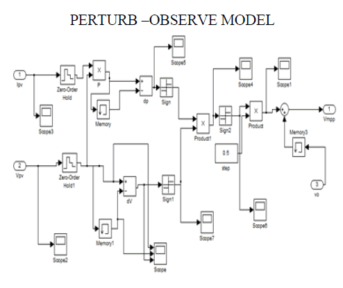 |
| Among all the methods, much focus has been on hill climbing and perturb and observe (P&O) methods. Hill climbing involves a perturbation in the duty ratio of the power converter, and P&O a perturbation in the operating voltage of the PV array. In the case of a PV array connected to a power converter, perturbing the duty ratio of power converter perturbs the PV array current and consequently perturbs the PV array voltage. it can be seen that incrementing (decrementing) the voltage increases (decreases) the power when operating on the left of the MPP and decreases (increases) the power when on the right of the MPP. Therefore, if there is an increase in power, the subsequent perturbation should be kept the same to reach the MPP and if there is a decrease in power, the perturbation should be reversed.. This algorithm also works when instantaneous (instead of average) PV array voltage and current are used, as long as sampling occurs only once in each switching cycle. The process is repeated periodically until the MPP is reached. The system then oscillates about the MPP. The oscillation can be minimized by reducing the perturbation step size. However, a smaller perturbation size slows down the MPPT. A solution to this conflicting situation is to have a variable perturbation size that gets smaller towards the MPP as shown in fig.9. |
| Once the direction for the change of voltage is known, the voltage is varied at a constant rate. This rate is a parameter that should be adjusted to allow the balance between faster response and less fluctuation in steady state. A modified version is obtained when the steps are changed according to the distance of the MPP, resulting in higher efficiency. This is an excellent method to reach the MPP, and it is independent from the PV panel, however, this method may suffer from fast changes in environmental conditions. The implementation Improvements can be obtained through a digital controller, transforming the conventional P&O into an adaptive solution once different step sizes according to the distance of the MPP are performed. In steady state, the operation point is not altered unless changes in environmental conditions happen. The key idea is to reduce to zero the dP/dV using a closed-loop control performing the P&O based on PI. |
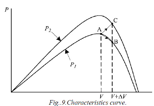 |
| Starting from an operating point A, if atmospheric conditions stay approximately constant, a perturbation ΔV in the PV voltage V will bring the operating point to B and the perturbation will be reversed due to a decrease in power. However, if the irradiance increases and shifts the power curve from P1 to P2 within one sampling period, the operating point will move from A to C [2]. |
| This represents an increase in power and the perturbation is kept the same. Consequently, the operating point diverges from the MPP and will keep diverging if the irradiance steadily increases. To ensure that the MPP is tracked even under sudden changes in irradiance uses a three-point weight comparison P&O method that compares the actual power point to two preceding ones before a decision is made about the perturbation sign. The sampling rate is optimized, while in toggling has been done between the traditional hill climbing algorithm and a modified adaptive hill climbing mechanism to prevent deviation from the MPP. |
VII. SIMULATION RESULTS AND PERFORMANCE EVALUATION |
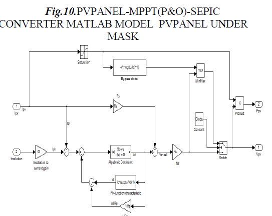
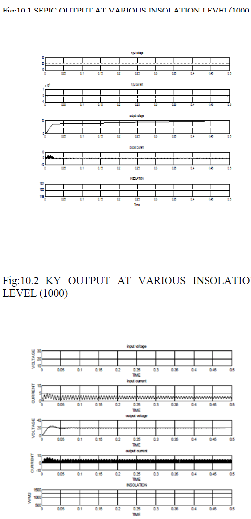
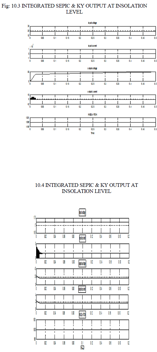
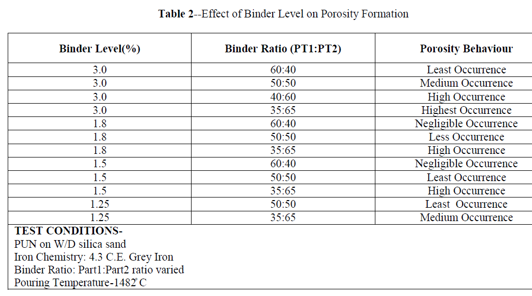
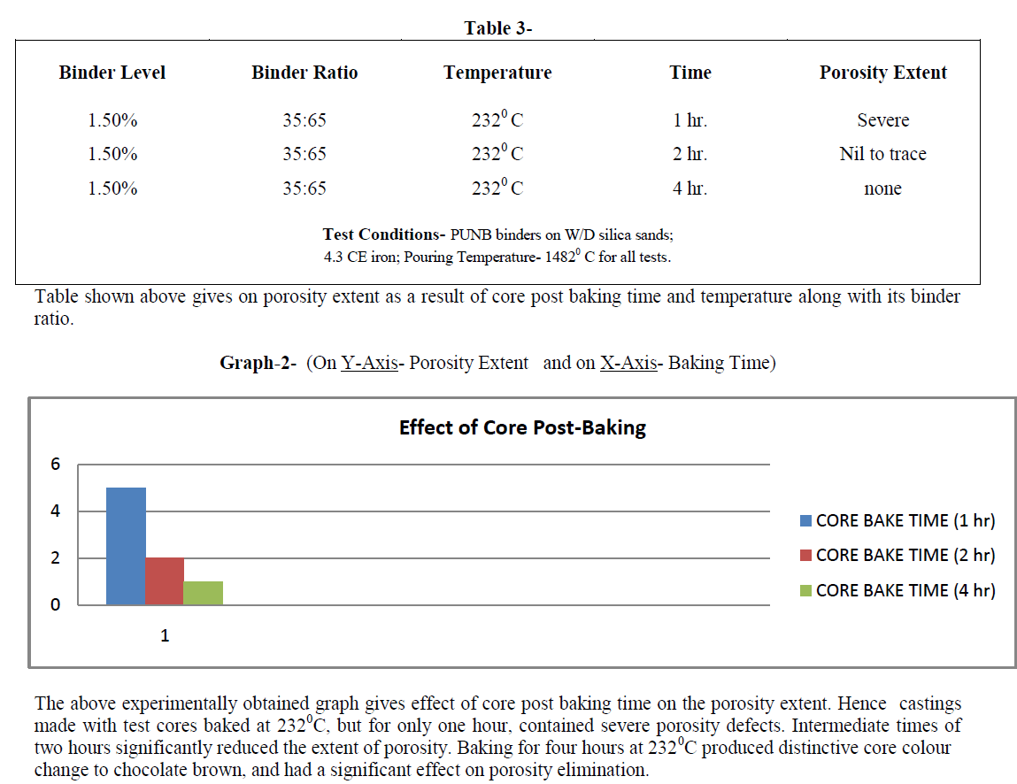
| The designed solar-PV system is simulated using Matlab/ Simulink, and its performance evaluation is carried out for different insolation, temperature, load, and duty cycles. The system performance for the variation in solar irradiance and due to this the MPPT controller operation to track, new operating point is presented. It can be observed that the solar radiation is increased at the time 0.5s, from 1000W/ m2 to 1400W/m2 and at the time 0.6s, it decreases to 1250W/ m2 from 1400W/ m2. As the radiation varies the MPPT controller tracks the new operation point and the voltage and current of the PV array are set to the new values. The voltage of the PV array is set to 16V from 18V at the time 0.5S, and at the time 0.6s it obtained a value of 17.2V. It is also observed that the DC-DC converter is providing a constant dc link voltage for the battery charging in spite of change in PV array voltage. In these results, G is the solar radiations, Pv is the output power from the solar PV array, Vpv is output voltage of PV array, Ipv is output current of PV array, Vc is output voltage of the SEPIC |
| DC-DC converter, VB and IB are voltage and current of the battery, Vo and Io are output ac voltage and load current. The performance of the feedback controller used in the VSI and the system results are obtained for the load variations. It can be observed that the consumer load is increased at the time 0.5s, to 250W from 100W and at the time 0.65s, it is again decreased to 100W. The environment conditions are considered to be constant at solar radiation level of 1000W/ m2,1250 W/ m2,1400 W/ m2 thus the output voltage and current of the PV array remain constant. The variation in battery current can be observed under the change in consumer loads. The system performance can be observed with the device currents and voltages for the system under linear load condition. |
| In these results, Vc is the voltage across the input capacitor Ci, Ici is the current through the input capacitor Ci. Vco is the voltage across the output capacitor Co, Ico is the current through the output capacitor. For the performance measure in nonlinear load conditions, a full bridge diode rectifier with RC in parallel combination is considered as a single phase nonlinear load. It can be observed that the solar radiation is increased at time 0.6s, to 1400W/ m2 from 1000W/ m2. The power output from the solar PV array is increased at the time 0.6s due to increase in the radiation. The MPPT controller now tracks a new operating point for the panel voltage and current as 44V and 0.012A |
 |
SIMULATION RESULTS |
 |
 |
 |
 |
 |
CONCLUSION |
| A low power standalone solar PV energy generation system with an integrated SEPIC & KY converter has been analyzed and the performance of the system has been presented under variation in solar radiations, loads, and duty cycles. The MPPT controller has been designed and it has performed satisfactorily for the tracking of new operating point for the solar PV system. The system has also been evaluated for the different loads and from the results obtained it has been observed that the system is withstanding in severe nonlinear situations with the harmonic distortion maintaining within limits. The experimental waveforms at a different load condition and the overall waveforms are agreed well with the theoretical analysis. It is shown that the voltage stresses on switching devices are limited to the output of boost converter Vo1 , which is slightly higher, neglecting the voltage spike caused by the parasitic inductance. |
References |
|