ISSN ONLINE(2319-8753)PRINT(2347-6710)
ISSN ONLINE(2319-8753)PRINT(2347-6710)
Dr.Hemachandra Reddy K1, Dr.Naga Malleshwara Rao G2
|
| Related article at Pubmed, Scholar Google |
Visit for more related articles at International Journal of Innovative Research in Science, Engineering and Technology
External natural convection heat exchangers have evolved as a suitable alternative to forced convection as a means to transfer energy from hot fluid to cold fluid in hot water storage tanks. Determination of performance characteristics of these convection heat exchangers require complicated and lengthy experiments and such a practical problem has been raised during the experimentation of a research work in the heat transfer laboratory. This work uses ANSYS to predict the intensity of thermal stresses induced during heat transfer in the walls of heat exchanger and to find optimum thickness of heat exchanger wall without affecting heat transfer rate. In this research work a heat exchanger wall with two different thickness values 1.2 mm & 1.5 mm is modeled through ANSYS to study the behaviour of thermal gradient.
Keywords |
| External natural convection heat exchangers, ANSYS, heat transfer in the walls of heat exchanger, optimum thickness of heat exchanger wall. |
INTRODUCTION |
| Solar hot water systems offer an environmental friendly way to transfer solar radiation directly to thermal energy for heating water. In the last decade, the utilization of solar energy as a sustainable alternative to fossil fuel for water heating has received favorable attention and as a result, the world market for solar hot water products has increased significantly. These systems achieved a substantial energy savings, and a sufficient reduction of CO2 emissions annually. This has led to the development of cost-effective systems, including new concepts to reduce manufacturing cost, improve performance and optimize the energy utilization. |
| The most common design of Solar Domestic Hot Water Systems (SDHWS) involves the use of a heat exchanger to transfer heat from the hot fluid to the water in the storage tank. Several heat exchanger configurations have been employed and the following configurations are among the most common. |
| (i) Immersed coil or immersed tubes that are the heat exchanger installed inside the storage tank. |
| (ii) External shell and tube heat exchanger with hot fluid pumped through the tubes and tank water (driven by natural convection) flowing through the wall. |
| (iii) The mantle heat exchanger (MHE) – in either its vertical form or the horizontal form consists of narrow annular jacket around the storage tank in which the hot fluid flows.[4] |
| The work presented in this paper involves assessment of the heat exchange characteristics and evaluations of the longterm performance of a mantle heat exchanger for solar domestic hot water system A MHE is a cylindrical storage tank surrounded by an annulus through which hot fluid flows by transferring energy to the tank contents. The separating wall is the heat exchange surface. Fig. 1 shows a typical SDHW system with a vertical mantle heat exchanger where the tank serves as both solar tank and the auxiliary tank. |
 |
II. SALIENT FEATURES OF THE MANTLE HEAT EXCHANGER SYSTEM |
| i). Thermal Stratification: The mantle tank system is one of the simplest ways of producing high heat exchanger effectiveness while promoting thermal stratification. The mantle configuration provides a large heat transfer area and effective distribution of the collector loop flow over the wall of the tank. Most of the incoming mantle fluid seeks the thermal equilibrium level in the mantle, and thermal stratification in the mantle and the inner link is not disturbed [1]. |
| ii). Cost: The cost of tank is less compared to the increased performance initiated by the fine thermal stratification [2]. |
| iii). Size limitation: The mantle tank design is not suitable for large low flow SDHW systems, as the heat transfer area gets too small for tanks with volumes over 800-1000 litres. [3]. |
III. EXPERIMENTS IN LABORATORY |
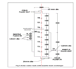
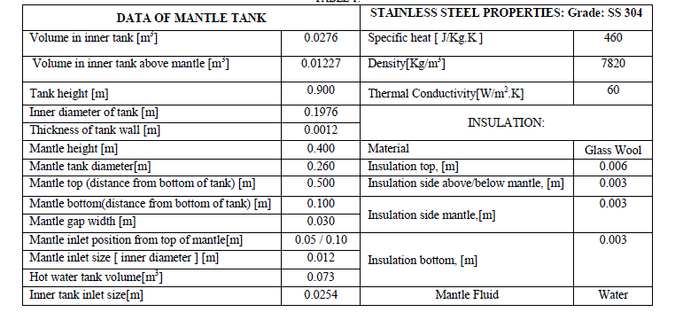
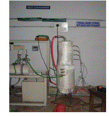
| A vertical mantle type heat exchanger with the dimensions as shown in figure 2 is fabricated for the purpose of experimentation. The experimental set up is shown in figure 3. The mantle tank data is given in table 1. |
 |
IV. MANTLE HEAT EXCHANGER PERFORMANCE MEASUREMENTS |
| An experimental arrangement is illustrated in fig 2 is set up to evaluate the overall heat transfer characteristics of the MHE and for the purpose of heat transfer coefficient measurements in the heat exchanger covering a range of mantle flow rates and thermal boundary conditions. These experiments are carried out at Heat Transfer Laboratory of JNT University, Anantapuram of Andhra Pradesh, India. |
 |
| The mantle is constructed with an annular spacing of 30mm wrapped around the bottom half of a stainless steel (SS304 Grade) tank. The tank is insulated with glass wool. In the experiments, hot water is supplied to the hot side of the heat exchanger from a conventional hot water tank as the heat source. |
| A schematic diagram of the indoor experimental setup is illustrated in fig 2 together with the instruments installed for the tests. Eight thermocouples made up of copper-constantan are fitted at different levels inside the core of the tank (fig1) and four thermocouples made up of copper-constantan are mounted on the mantle tank wall side of the heat exchange surface, to measure tank temperatures at different locations and to know the stratification. The inlet & outlet temperatures and flow rate of the hot water (mantle fluid) through the heat exchanger are also measured. The thermocouples are used to measure the temperatures of selected locations in the tank. 31/2 digit digital display is used to display the temperatures. |
V. PROCEDURE FOR ANSYS ANALYSIS |
| Static analysis is used to determine the displacements, stresses, strains and forces in structures or components due to loads that do not induce significant inertia and damping effects. Steady loading in response conditions are assumed. The kinds of loading that can be applied in a static analysis include externally applied forces and pressures, steady state inertial forces such as gravity or rotational velocity imposed (non zero) displacements, temperature (for thermal strain). A static analysis can be either linear or non linear. In our present work we are going to consider linear statistic analysis. |
| The procedure for static analysis consists of these main steps: |
| ïÃâ÷ Building the model |
| ïÃâ÷ Obtaining the solution. |
| ïÃâ÷ Reviewing the results. |
| ïÃâ÷ Build the model. |
A. Building the model |
| In this step, the job name is specified and analysis title use PREP7 to define the element types, element real constraints, material properties and the model geometry element types both linear and non linear structural elements are allowed. The ANSYS elements library contains over 80 different element types. A unique number and prefix identity for each element type. Example: BEAM94, PLANE71, SOLID96 and PIPE16. |
B. Material properties |
| Young’s modules (Ex), Must be defined for a static analysis. If we plan to apply inertia loads (such as gravity) we define mass properties such as density (DENS). Similarly if we plan to apply thermal loads (temperatures); we define coefficient of thermal expansion. |
C. Obtain the solution |
| In this step we define the analysis type and options, apply loads and initial conditions the finite element solution. This involves three phases: |
| 1) Pre processor phase. 2) Solution phase. 3) Post processor phase. |
1) Pre-processor |
| Pre processor has been developed so that the same program is available on micro, mini, super mini and main frame computer system to other. Pre processor is an interactive model builder to prepare FE (finite element) model and input data. The solution phase utilizes the input data developed by the pre processor, and dies the solution according to the problem definition. It creates input files to the temperature, etc., on the screen in the form of contours. The following section describes various capabilities and features of the pre-processor. |
2) Solution |
| The solution phase deals with the solution of the problem according to the problem definitions. All the tedious work of formulating and assembling of matrices are done by the computer, and finally displacements and stress values are given as output. Some of the capabilities ANSYS are linear static analysis, transient dynamic analysis etc. |
3) Post processor |
| It is a powerful user-friendly post processing program. Using interactive color graphics; it has extensive plotting features for displaying results obtained from the finite element analysis. One picture of analysis results (i.e., results in a visual form) can often reveal in seconds what would take an engineer hour to asses from a numerical output, saying a tabular form. The engineer may also see important aspects of the results that could be easily missed in a stack of numerical data. [5,6] |
VI. PROBLEM FORMULATION |
| A mantle heat exchanger is designed and fabricated as a part of research work (Ph.D.), of the author member with a wall thickness of 1.2 mm. but a practical problem has risen while altering tried to provide extra fittings over the heat exchanger. Initially small thickness of 1.2 mm is chosen to have very effective heat transfer between the hot and cold fluids. Hence to avoid the fabrication problems without affecting the heat transfer rates an attempt is made to increase the wall thickness from 1.2 mm to 1.5 mm and the behaviour of thermal stresses induced during heating process is also studied. Structural stresses are also analysed using ANSYS. |
VII. RESULTS |
| After modeling the mantle heat exchanger by going through the procedure explained above, the obtained results are tabulated and discussed. The properties of material selected in this study are given below: |
| Thickness of tank wall = 1.2 mm , |
| Material = stainless steel (SS: 304) |
| Specific heat = 460 J/kg.k |
| Density = 7.82 gm/m3 |
| Thermal conductivity = 15 w/m2.k |
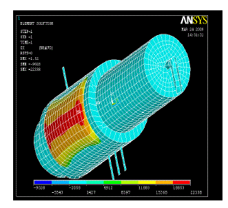 |
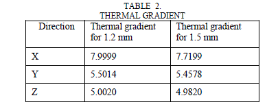
| The maximum Thermal gradient observed in X-direction, Y-direction & Z-directions for 1.2 mm and 1.5 mm are as shown in table 2. |
 |
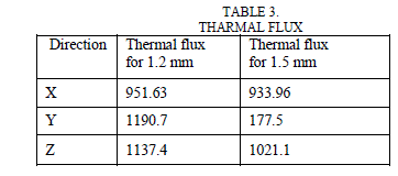
| The maximum Thermal flux observed in X-direction, Y-direction & Z-directions for 1.2 mm and 1.5 mm is as shown in table 3. |
 |
VII. CONCLUSION |
| From the above study, the thickness of heat exchanger wall can be increased from 1.2 mm to 1.5 mm, as there is no declination in heat transfer rates. It is observed from the result table that, the maximum thermal gradient is 7.999 in X direction and the maximum thermal flux is 1190.7 in Y-direction for 1.2 mm thick wall. It is observed from the result table that, the maximum thermal gradient is 7.7199 in X direction and the maximum thermal flux is 1077.5 in Ydirection for 1.5 mm thick wall. As there is no difference in heat transfer rates and moreover the thermal stresses can be reduced if the thickness is increased to 1.5 mm. There is a slight increase in the cost of product, which can be afforded by compensating with the performance of heat exchanger. |
References |
|