ISSN ONLINE(2319-8753)PRINT(2347-6710)
ISSN ONLINE(2319-8753)PRINT(2347-6710)
K. Hemanth (M. Tech) 1
|
| Related article at Pubmed, Scholar Google |
Visit for more related articles at International Journal of Innovative Research in Science, Engineering and Technology
This paper presents the design and implementation of an energy management system (EMS) with fuzzy control for a dc microgrid system. Modeling, analysis, and control of distributed and energy storage devices with MATLAB/Simulink are proposed. To improve the life cycle of the battery, fuzzy control manages the desired state of charge. A fuzzy network has been designed to control the operating mode the battery to monitor values of all subsystems in the dc microgrid system.
Keywords |
| fuzzy control, microgrid |
INTRODUCTION |
| With increased awareness of the depletion of traditional energy sources and environmental damage caused by increased carbon dioxide emissions from coal-fired power generation, the use of renewable energy has become the goal for energy development. Current green energy used in power generation includes: solar, wind, geothermal, biomass, and tidal [1]. Many countries have set a goal of increasing the usage of renew-able energy above 20% of their total power consumption by the year 2020. In addition, distributed power systems are subject to the effects of environmental factors and restrictions of nature. A general power system uses battery energy storage to avoid a power outage or power surges caused by natural environmental factors. The recent trend of renewable energy development is a combination of distributed power sources and energy storage subsystems to form a small microgrid [2], [3] that can reduce loss of energy from power transmission lines over long distances. Renewable energy is converted into dc and buffered with energy storage elements, and then it is inverted to ac and fed into the utility grid. This approach can readily adapt to existing electrical facilities and expedite use of renewable energy. However, existing high efficiency and compact appliances and equipment are powered by dc, which is converted by rectifying |
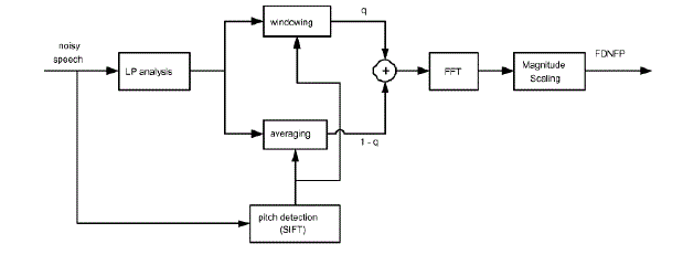 |
| Such a supply scheme is far different from that of the conventional ac distribution and supply system. A configuration of the dc-distributed system with grid connection is shown in Fig. 1, in which a bidirectional inverter is introduced to regulate dc-grid voltage within a certain range. |
| DC-distributed systems were applied to data centers [4]–[14], which reduced power loss by around 7%, saved 33% of space, reduced facility investment by about 15% and increased reliability by about 200% [1]. Additionally, low voltage (24 V) ceiling-grid applications, especially for lighting, were also developed 15]–[19]. There are several research groups [20]–[33], which have extended the high voltage (380 V) dcdistribution system to drive home appliances, of which the elegant power application research center (EPARC) has built a demonstration house for testing the overall system operation. In this pa-per, the system configuration including green power generator, energy storage element, dc appliance and equipment, and energy management system (EMS) with a fuzzy controller will be introduced. |
| In the development of the green energy systems, a control method is required to optimize energy distribution of a microgrid system. Therefore, model construction is necessary for solar energy, wind power, and storage devices, such as lithium-ion batteries, to simulate dynamic changes of the renewable energy for optimal energy distribution. |
| Fig. 1 shows the dc microgrid system in this study, composed of solar power, wind power generation, lithium-ion battery, dc load, and ac/dc converter. The proposed EMS was commanded with RS-485/ZigBee [34], [35] network for data communication and delivery of energy distribution instructions. The design concept of this study was to increase the useful life of lithium batteries and to include charge and over discharge protection mechanisms. |
| As shown in Fig. 1, the system configuration includes five major blocks: power generator, energy storage equipment, dc-bus regulator, dc load, and EMS. The power generator typically includes PV panels, wind turbines, and fuel cells. The fuel cells provide base power for the emergency loads when the system is operated during a power failure. Maximum power point track-ers are associated with PV panels and wind turbines to draw maximum power, which is fed into the dc grid. The dc loads are connected to the dc grid and supplied from the grid directly. If there is power shortage, the bidirectional inverter will take power from the ac grid and it is operated in rectification mode with power factor correction to regulate the dc-grid voltage within a range of 380 ± 20 V. |
| If there is a power failure, the Li-ion battery will be first discharged to supply power for a short-time interval and if the failure lasts longer (e.g., 2 min), the fuel cell will start supplying power. Note that the battery discharger will be also responsible for dc-grid voltage regulation if the bidirectional inverter is not in operation. |
| If the bidirectional inverter is in operation, the battery can be charged. |
| If there is residual power on the dc grid, the battery can be charged depending on its status, and/or the bidirectional inverter can be operated in grid-connection mode to sell power and regulate dc-grid voltage to 380 ± 20 V. The overall system operation will be monitored and controlled by the EMS, so each module in the system has to communicate with the EMS based on RS-485 or ZigBee communication protocol. The EMS will command the modules when to operate and collect operational status. How-ever, in emergency situations, such as excessive current, voltage or temperature, the modules will protect themselves without a command from the EMS, but the modules still have to inform the EMS of their current status. |
| The proposed fuzzy control is to optimize energy distribution and to set up battery state of charge (SOC) parameters. The control algorithm takes the priority of selling electricity as the premise of energy distribution to allow remaining power generated by the renewable energy of the electrical grid sold through the connected mains grid. |
II. MODELING OF GREEN ENERGY COMPONENTS |
| To verify the accuracy of the designed controller, a dynamic model of the proposed microgrid system is necessary. The modeling of dc microgrid distributed energy and energy storage components were mainly built by MATLAB simulink mathematical modules, based on equivalent circuits of the components. The following describes the model of each subsystem in detail. |
 |
A. Modeling of Solar Cell |
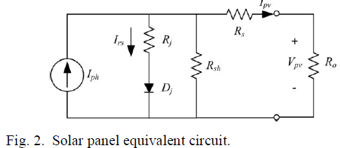
| Solar panel equivalent circuit is shown in Fig. 2. |
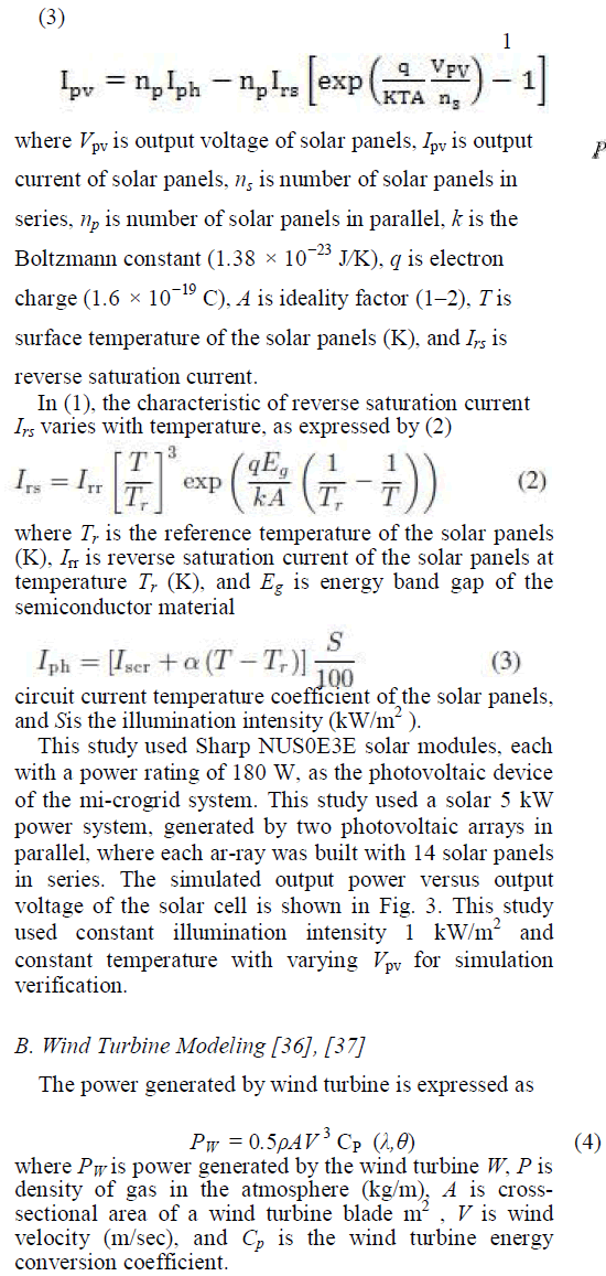
| Solar panel current equation can be expressed by (1)– |
 |
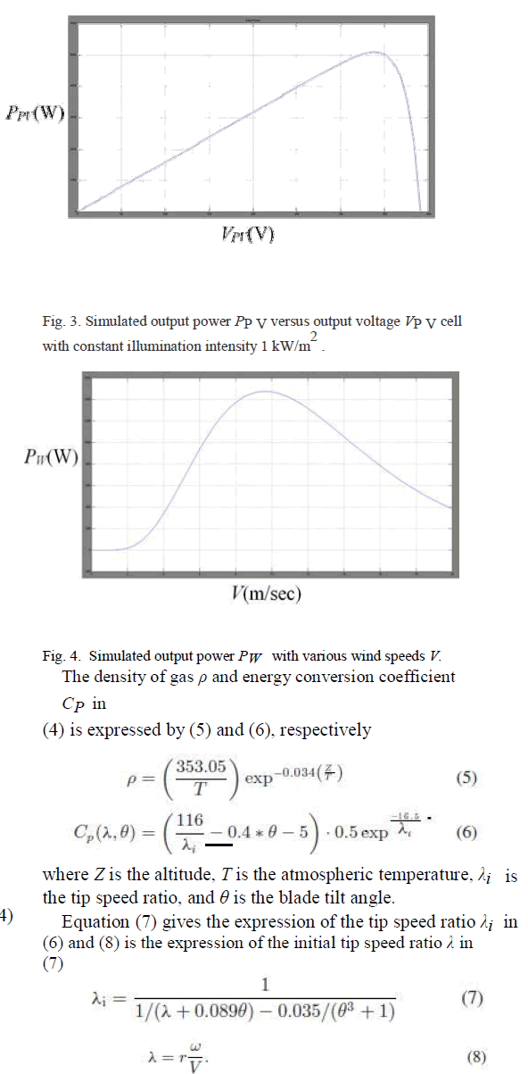 |
| The wind turbine used in this study was AWV-1500 of Gallant Precision Machining Company, Ltd. Wind speed is the most critical factor in wind power generation. This simulated output power PW of the wind turbine with various wind speeds V is shown in Fig. 4. |
C. Lithium-Ion Battery Modeling |
| Eq. (9) is the discharge equation and (10) the charge equation of the lithium-ion battery |
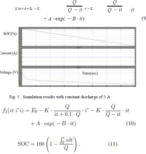 |
| This study simulated with constant discharge of 5 A for vali-dation and observation of SOC variation. The results are shown in Fig. 5. The battery voltage is easy to measure and implement in the circuit. From the simulated results, we can see the nonlin-earity between voltage and SOC of the Li-ion battery. Therefore, the SOC parameter of batteries has been selected as the design factor instead of battery voltage in this paper. |
D. Fuel Cell Modeling |
| Fuel cells provide a high efficiency clean alternative to today’s power generation technologies. The polymer electrolyte membrane (PEM) fuel cell has gained some acceptance in medium power commercial applications such as creating backup power, grid tied distributed generation, and electric vehicles [1]. The output voltage E of the PEM fuel cell is represented as |
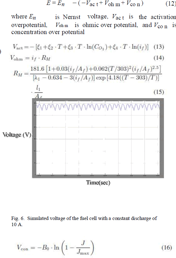 |
| where T is operating absolute temperature, Co2 is concentra-tion of oxygen, if is output current of the fuel cell, ξ1 ,2 ,3 ,4 are reference coefficients, l1 is effective thickness of membrane, λ1 is adjustable coefficient, Af is effective area, B0 is operating constant, J is current density, and Jma x is maximum current density. |
| The simulated output voltage with constant discharge of 10A is shown in Fig. 6. |
III. INTELLIGENT ENERGY MANAGEMENT SYSTEM |
| As shown in Fig. 1, the system configuration of the proposed dc microgrid system includes five major blocks. To design an accurate controller of the proposed microsystem, the dynamic mathematical models of the power sources (PV, wind turbine, and fuel cell), dc/dc converters (buck-boost, buck, and phase-shifted fullbridge converters), bidirectional converter (sym-metrical full-bridge converter), and bidirectional inverter (fullbridge inverter) of the integrated micro-system are necessary. However, the modeling, analysis, and design of the proposed integrated dc microsystem are not simple. To maintain the battery SOC with EMS, the fuzzy controller is needed to meet design specifications, because the control for EMS is a low response component and the models of dc/dc converters, dc/ac converters of the micro-dc microgrid system are unnecessary. Additionally, the dc microsystem is a nonlinear system and fuzzy logic can offer a practical way for designing nonlinear control systems. |
| Fuzzy control theory is designed and implemented in EMS for the dc microgrid system to achieve the optimization of the system. The design criterion requires that both the photovoltaic device and the wind turbine are supplied by a maximum power point tracker to maintain the maximum operating point. The difference between actual load and total generated power is taken into account for Li-ion battery in charge and discharge modes. The life cycle and SOC of the battery are in direct proportion. To improve the life of the Li-ion battery, we can control and maintain the SOC of battery with fuzzy control. |
 |
A. Fuzzy Control |
| Fuzzy theory was first proposed in 1965 by Lotfi. A. Zadeh, an American scholar of automatic control, as a tool of quantitative expression for concepts that could not be clearly defined. A fuzzy control system is based on fuzzy-logic thinking in the design of how a controller works. The so-called fuzzy logic is to establish a buffer zone between the traditional zero and one, with logic segments of none-zero and none-one possible. It allows a wider and more flexible space in logic deduction for the expression of conceptual ideas and experience. A fuzzy controller differs from a traditional controller in that it em-ploys a set of qualitative rules defined by semantic descriptions [38]–[40]. |
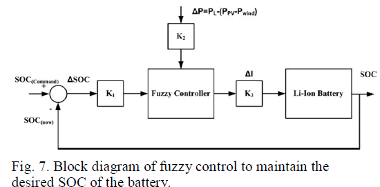
| The fuzzy controller is applied in the proposed microgrid power supply system, as shown in Fig. 7. To obtain the desired SOC value, the fuzzy controller is designed to be in charging mode or discharging mode for the proposed microgrid system. The input variables of the fuzzy control are ΔSOC and P and output variable is I. The definition of input and output variables are listed as follows: |
 |
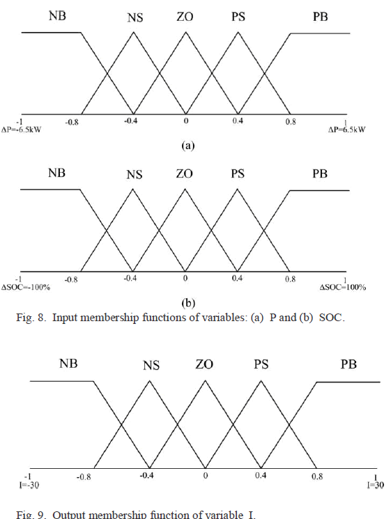
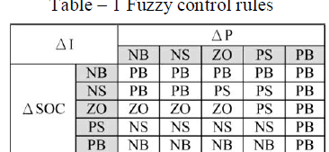
| The power difference P is between required power for load and the total generated power of the microgrid. The fuel cells only provide base power for the emergency loads when the system fails. Therefore, the fuel cell is not considered as power source in (18). The generated power comes from solar power Ppv , wind turbine P win d and power load PL for the proposed system. The input and output membership functions of fuzzy control contain five grades: NB (negative big), NS (negative small), ZO (zero), PS (positive small), and PB (positive big), as shown in Figs. 8 and 9. By input scaling factors K1 and K2 , we can determine the membership grade and substitute it into the fuzzy control rules to obtain the output current for charge and discharge variance I of the Li-ion battery. If the P is negative, it means that the renewable energy does not provide enough energy to the load. Thus, the battery must operate in charging mode; if the ΔSOC is negative, it means that the SOC of the battery is greater than the demand SOC. Thus, the battery must operate in discharge mode. |
 |
| The control rules of this study prioritize selling additional electricity generated by the renewable energy in response to the present control strategy of microgrid development for selling electricity and increasing the life of Li-ion batteries. Table I shows the fuzzy rules of the proposed system. For example, the output variable I is PB (the degree of discharging current is large) when the input variable P is NB (the amount of elec-tricity to sell is large) and input variable ΔSOC is NS (greater than the SOC command and the membership degree is small). However, the output variable I is NS (the degree of charging current is small) when the input variable P is NB (the amount of electricity to sell is large) and input variable ΔSOC is PS (smaller than the SOC command and the membership degree is small). The output variable is NS instead of NB when the system is operated in the above conditions because selling electricity is the first priority in this case. Thus, the fuzzy control table of the proposed dc microgrid system is not symmetrical. To extend the life of storage batteries in the design of fuzzy control, the fuzzy control rules are set to maintain battery SOC above 50%. Moreover, in the fuzzy control rules the Li-ion battery is forced to discharge as the control strategy when power demand at load was greater than the power generated by the renewable energy. |
B. Illustration Example |
| The dynamic model of the proposed dc microgrid system using MATLAB simulink is shown in Fig. 10, where the system consists of a 5 kW solar module, a 1.5 kW wind turbine module, a 1.5 kW Li-ion battery module, and a 6.5 kW l oad. |
 |
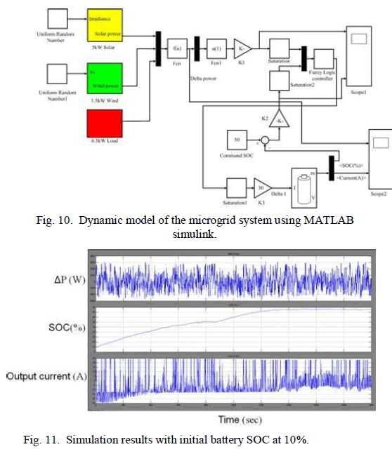 |
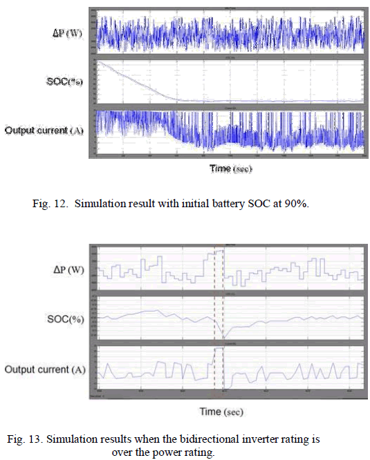
| This example verifies the accuracy of the proposed system with fuzzy controller that can maintain the SOC of the battery at a certain level whether initial value of the SOC is low or high. As shown in Fig. 11, the fuzzy controller Li-ion battery SOC is maintained at 50% with an initial value of 10%. As shown in Fig. 12, the fuzzy controller Li-ion battery SOC is maintained at 50% with an initial value of 90%. |
| To control strategy of this study is to sell electricity as a priority and to maintain battery SOC. Fig. 13 shows that the fuzzy controller forced the Li-ion battery to discharge when P was greater than 5 kW to keep the system in power equilibrium without going over the power rating of the bidirectional inverter subsystem. However, the SOC of the battery is not the first priority to achieve the safety when the inverter is over the power rating. |
 |
V. CONCLUSION |
| This paper presents the modeling, analysis, and design of fuzzy control to achieve optimization of an energy management system for a dc microgrid system. From the simulation results, the system achieves power equilibrium, and the battery SOC maintains the desired value for extension of battery life by using the control rules for a dc microgrid. Additionally, the optimization rules can be included in the intelligent microgrid management system, and the system can conduct data communication and control operating status of subsystems via the RS-485/ZigBee network. The management system takes advantage of the design to control microgrid with power equilibrium, and achieves optimal control of the dc microgrid system. |
References |
|