ISSN ONLINE(2319-8753)PRINT(2347-6710)
ISSN ONLINE(2319-8753)PRINT(2347-6710)
Monica S Swamy 1, Ranjith A 2, Sandya D S 2, Shrithi S Badami2
|
| Related article at Pubmed, Scholar Google |
Visit for more related articles at International Journal of Innovative Research in Science, Engineering and Technology
The usage of heterogeneous materials in situations where large strength to weight ratio is required has been increased substantially over the world in all construction aspects. The behaviour of the plate under each loading is different. Whenever the delamination is located at the middle plane of laminate, the panel exhibits only global buckling, i.e. there is no buckling of delaminated region. Whenever the delamination is close to the surface, the buckling mode is predominantly local. The type of plate also plays a major role in carrying load. This article summarises the numerical study carried out using finite element software ANSYS and Timoshenko’s methodology to examine the buckling behaviour of homogeneous and heterogeneous plate element with and without crack. Also the effect of aspect ratio on the buckling behaviour with varying plate thickness for different boundary conditions was also examined.
Keywords |
| Buckling Analysis, Plate Element, Finite Element Analysis, Aspect ratio, Buckling load |
INTRODUCTION |
| Buckling analysis is a type of analysis used to determine buckling loads - critical loads at which a structure becomes unstable. Buckling behaviour significantly changes with change in aspect ratio, thickness of the element as plates are subjected to different end conditions. Plate seems to work as a column of finite width at higher aspect ratio. If we decrease aspect ratio, there is also a limit below which failure does not take place by elastic buckling. When the opening becomes inevitable for the plates under large working stress, the reduced buckling strength of the plate may be insufficient to meet the requirements of normal serviceability limits and structural safety. A design solution must be deduced to increase the structural stability of such perforated plate before it can be used to its best advantage. This always can be accomplished by selecting the thicker plate but the design solution may not be economical in terms of weight of material introduced by an adequate increase in the thickness of the plate. |
| The present work deals with the analysis of a rectangular element being considered as a plane stress condition under various boundary conditions and loadings. Throughout the analysis, the master element which is plane 82 are used to perform buckling analysis using ANSYS. Finally, results have been checked with exact results obtained from Timoshenko’s plate buckling equation for different end conditions. |
| Jana et al. [1] carried out a buckling analysis of a simply supported rectangular plate without cut out subjected to various types of non-uniform compressive loads. Chai et al. [2] investigated the influence of boundary conditions, plate aspect ratios on the optimal ply angle and associated optimal buckling loads of anti-symmetrically laminated composite plates without cut out under various linearly varying in-plane loading conditions. Hu et al. [3] examined the buckling behaviour of a graphite/epoxy symmetrically laminated composite rectangular plate without cut out under parabolic variation of axial loads. Jain et al. [4] investigated the effects of the cut out shape, size and the alignment of the elliptical cut out on the buckling and the first-ply failure loads of square laminates subjected to uni-axial compression load. Aydin Komur et al. [5] investigated the effects of an elliptical/circular cut out on the buckling load of symmetric cross-ply and angle-ply laminate square composite plates. |
| The work in this paper is divided in two stages: 1) Modelling of homogeneous and heterogeneous plate with and without crack 2) buckling analysis for inter-laminar crack growth in homogeneous and heterogeneous plates for different plate thickness with varying aspect ratio. |
BUCKLING ANALYSIS |
| The buckling of homogeneous plates has been well researched and documented for decades. Various methods, such as energy and equilibrium methods, have been used to determine the lowest eigen value, or the actual buckling load. The results of these methods are given in this work and the reader is referred to Timoshenko’s’ Theory of Elastic Stability [7] for a more comprehensive treatment of homogeneous plate buckling. For a homogeneous plate the following formula is used to determine the critical buckling load per unit length: |
 |
| Where, E is Young’s Modulus, ÃÅ Ãâ¹ is Poisson’s ratio, t is the plate thickness, b is the width of the plate, and k is a constant determined by the boundary condition and aspect ratio of the plate. Timoshenko [7] gives values of k for various aspect ratios under various edge boundary conditions. |
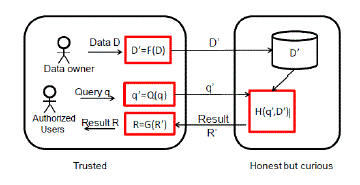 |
| Figure 1 shows the influence of various support conditions in selecting the coefficients of buckling for determining critical buckling load per unit length of a plate element subjected to in plane loading as suggested by Timoshenko. |
| 2.1 Element Type used in ANSYS |
| The element used in the analysis is PLANE82. PLANE82 is a higher order version of the 2-D, four node element (PLANE42). It provides more accurate results for mixed (quadrilateral-triangular) automatic meshes and can tolerate irregular shapes without as much loss of accuracy. The 8-node elements have compatible displacement shapes and are well suited to model curved boundaries. The 8-node element is defined by eight nodes having two degrees of freedom at each node: translations in the nodal x and y directions. The element may be used as a plane element or as an axisymmetric element. The element has plasticity, creep, swelling, stress stiffening, large deflection, and large strain capabilities. |
| PLANE82 Assumptions |
| ïÃâ÷ The area of the element must be positive. |
| ïÃâ÷ The element must lie in a global X-Y plane "PLANE82 Geometry" and the Y-axis must be the axis of symmetry for axisymmetric analyses. An axisymmetric structure should be modeled in the +X quadrants. |
| ïÃâ÷ A face with a removed mid-side node implies that the displacement varies linearly, rather than parabolic variation along that face. |
| PLANE82 Restrictions |
| ïÃâ÷ The DAMP material property is not allowed. |
| ïÃâ÷ Influence body loads are not applicable. |
| ïÃâ÷ The only special feature allowed is stress stiffening. |
ANALYSIS |
| A) Homogeneous Plate |
| 3.1.1 Analytical detail |
| Homogenous plate is assumed as Aluminium Alloy which in nonferrous metal with the following material properties. |
| Density of Aluminium =2700kg/m3 |
| Poisson’s ratio of Aluminium=0.3 |
| Young’s modulus of Aluminium=7x10¹⁰pa |
| 3.1.2 Modelling |
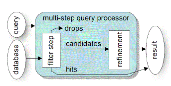 |
| Figure 2 shows metal block of size 1m x 0.5m which was modelled as 2-D model and meshed with approximately 16 elements across the width of the metal block. |
| 3.1.3 Buckling analysis |
| Buckling analysis is a technique used to determine buckling loads - critical loads at which a structure becomes unstable - and buckled mode shapes - the characteristic shape associated with a structure's buckled response. Various methods, such as energy and equilibrium methods, have been used to determine the lowest eigenvalue, or the actual buckling load.For a homogeneous plate the following formula is used to determine the critical buckling load per unit length: Where, E is Young’s Modulus, Ãâ°Ã£ is Poisson’s ratio, t is the plate thickness, b is the width of the plate, and k is a constant determined by the boundary condition and aspect ratio of the plate. |
| The homogeneous plates analysed in ANSYS were given the following isotropic properties: |
| E = 7.0 X 10¹⁰ pa |
| Ãâ°Ã£= 0.30 |
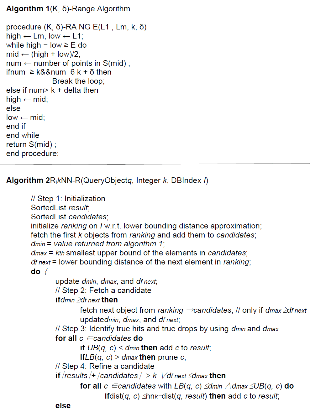
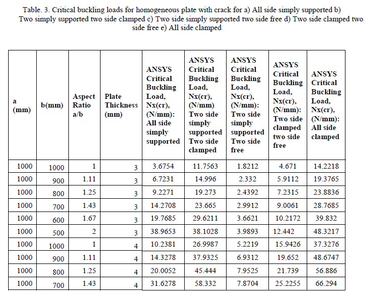
| The plates were analysed under three different boundary conditions: All sides simply supported, two sides simply supported two sides clamped, two sides simply supported two sides free, and all sides clamped. Three different plate thicknesses were used: 3mm, 4mm, and 5mm. For each plate thickness, four different aspect ratios (a/b) were used: 1.0, 1.11, 1.25, 1.43, 1.67, and 2.0. The length, a, was held constant at 1000mm and the width b, was varied between 1000mm, 900mm, 800mm,700mm,600mm, and 500mm. The critical buckling load results are tabulated in Table 1 and table 2. |
 |
 |
| B) Homogeneous Plate with Crack |
| 3.2.1 Analytical detail |
| Homogenous plate is assumed as Aluminium Alloy. A small crack is modelled at a distance 0.25m from top and 0.5m from the side edge, it is an elliptical shaped crack having dimension 0.04m in major axis and 0.0001m in minor axis. |
| Density of Aluminium =2700kg/m3 |
| Poisson’s ratio of Aluminium=0.3 |
| Young’s modulus of Aluminium=7x10¹⁰pa |
| Modelling |
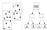 |
| Figure 3 shows homogeneous plate element with crack, Modelling is done using solid 82 type element in ANSYS. Because of elliptical shape a fine mesh is generated near crack tips. Except at the crack tips the whole model is meshed coarsely. Bottom extreme nodes are fixed. |
| Buckling analysis |
| Buckling analysis for homogeneous plate with crack is carried out for different plate thickness, end condition, aspect ratios as stated in 3.1.3. |
 |
 |
| 3.3 Laminated Heterogeneous Plate |
| 3.3.1 Analytical detail |
| Laminated heterogeneous plate is assumed as the combination of Aluminium and Low Carbon Steel with following material properties. |
| Material properties of low carbon steel: |
| Density of steel= 7872 Kg/m3 |
| Poisson’s ratio=0.29 |
| Young’s modulus of steel=2x10¹¹pa |
| Material properties of Aluminium: |
| Density of Aluminium =2700kg/m3 |
| Poisson’s ratio of Aluminium=0.3 |
| Young’s modulus of Aluminium=7x10¹⁰pa |
| 3.3.2 Modelling |
 |
| Figure 4 shows laminated heterogeneous plate element without crack. Since heterogeneous material is used, both aluminium and low carbon steel modelled with an interface in between. |
| 3.3.5 Buckling analysis |
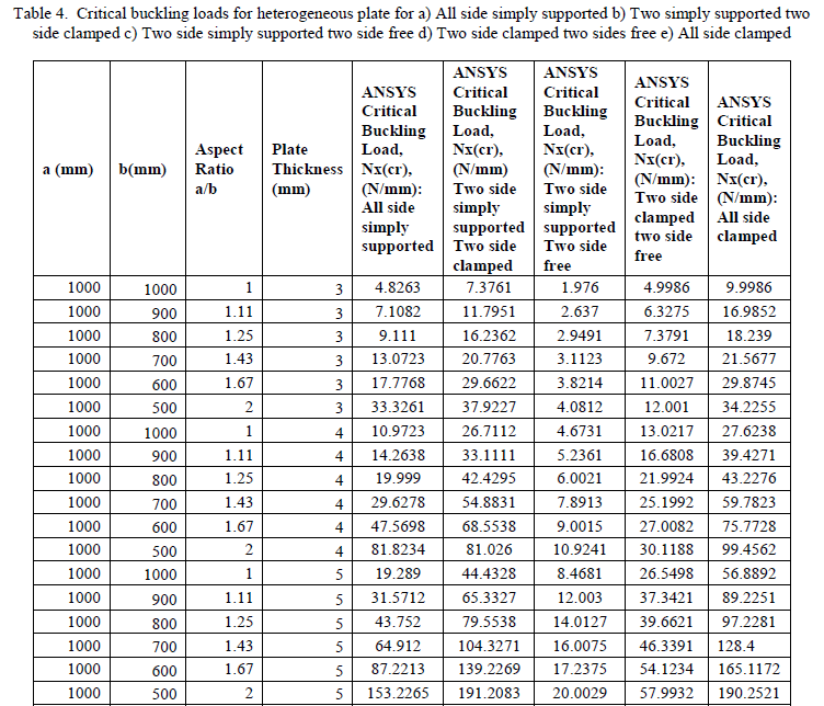
| The heterogeneous laminated plates analysed in ANSYS were given the following isotropic Properties: |
| For Aluminium laminate: E = 7.0 X 10¹⁰ pa |
| μ= 0.30 |
| For Low Carbon Steel laminate: E = 2.0 X 10¹¹pa |
| μ= 0.29 |
| The analysis is carried out for different plate thickness, end condition, aspect ratios as stated in 3.1.3. The corresponding buckling loads are tabulated in table 4. |
 |
| 3.4 Laminated Heterogeneous Plate with Crack |
| 3.4.1 Modelling |
 |
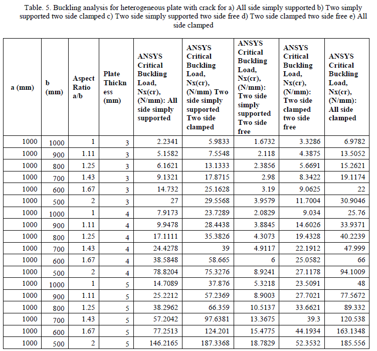
| Figure 5 shows laminated heterogeneous plate with interfacial crack. Heterogeneous material is assumed as the combination of Aluminium and Low Carbon Steel, the crack is situated exactly at the interface between steel and aluminium as shown in figure which is often called as interfacial crack occurs in the heterogeneous laminates, material properties of aluminium and low carbon steel are assumed as in the previous analysis. The analysis is carried out same as laminated heterogeneous plate but here the interfacial crack is introduced then the analysis is carried out for different thickness, aspect ratios, and end conditions. The critical buckling loads for different boundary conditions are tabulated in table 5. |
 |
CONCLUSION |
| Critical Buckling load for homogeneous plate is more compare to laminated heterogeneous plate |
| Buckling load per unit length of the plate decreases with increase in aspect ratio |
| It is noted that the presence of crack lowers the buckling load |
| The study is useful in selecting the above said parameters in designing the laminates in buckling point of view |
ACKNOWLEDGEMENT |
| Author would like to acknowledge and extend his heartfelt gratitude to the persons who helped for this research work and thankful to the Department of Civil Engineering, Adi Chunchanagiri Institute of Technology, Chikmagalur. |
References |
|