International Journal of Innovative Research in Science, Engineering and Technology
ISSN ONLINE(2319-8753)PRINT(2347-6710)
ISSN ONLINE(2319-8753)PRINT(2347-6710)
PratibhaSrivastav1, ManojJha2, M.F.Qureshi3
|
| Related article at Pubmed, Scholar Google |
Visit for more related articles at International Journal of Innovative Research in Science, Engineering and Technology
This paper presents the application of extended adaptive neuro-fuzzy inference system (ANFIS) for solving the power system stability problem. The issue of power system stability is becoming more crucial [1]. The excitation and governing control of generator play an important role in improving the dynamic and transient stability of power system. In this paper, the authors present an extended Neuro-fuzzy based method called coactive neuro-fuzzy inference system (CANFIS), for the excitation control and governing control. Among these techniques, generator control is one of the most widely applied in power industry. In this paper a coordination of governing control and excitation control using multiple-output ANFIS with nonlinear fuzzy rules called CANFIS model compensate their control inputs during faults [1]. The proposed CANFIS automatically coordinates the behavior of the two compensations. The observations show its satisfactory behavior for proposed control. A generalized ANFIS which is tuned by a Multilayer Perceptron (MLP) neural network has a modified version of ANFIS and it improves the power system response by fast damping of oscillations of internal angle of generator following different types of faults and different location of transmission line.
Keywords |
| Power System, Transient Stability, Fuzzy logic, Excitation and governing Control, Multilayer perceptron |
INTRODUCTION |
| Power system stability issue has been studied widely. Many significant contributions have been made, not only in the aspects of analyzing and explaining the dynamic phenomena, but also in the efforts of improving the stability of transmission systems[10]. Among these techniques, generator control is one of the most widely applied in the power industry [12]. This typically includes governing and excitation control. Most attention is directed toward the excitation control. |
| Most of excitation controls are based on SISO-PID control, MIMO linear control, optimal linear and nonlinear control, and intelligent control, such as applications of neural network and fuzzy logic and hybrid of these two i.e. neuro-fuzzy system [13]. In MLP tuned ANFIS i.e. CANFIS, the back propagation MLP is compared with locally tuning model CANFIS. |
| In power engineering area, fuzzy set theory is applied in power system control, planning and some other aspects[3]. The neural network has also been applied in power system control by developing neural controllers. Fuzzy logic has also been applied to design power system stabilizers. Governing system behavior is neglected in the design of excitation control. Part of the reason is the slow response of governing systems compared with exciting system [5]. However proper control of governing system is helpful in damping system oscillation and improving the transient stability[7-9]. |
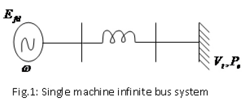
| In this piece of research work coordination of governing control and excitation control using neuro-fuzzy theories compensate their control inputs during faults. The angular speed(ω), accelerating speed (Pm − Pc) and the terminal voltage (Vt) of generator are observed to characterize the severe ness of oscillation [2]. The design of Neurofuzzy controller is applied to a single machine to infinite bus system [7]. A 3-phase fault is used as an example of system disturbances. SIMULINK simulation model is built to study the dynamic behavior of the synchronous machine and the performance of proposed controller [11]. The simulation results are demonstrated in the following sections [14]. |
NEURO-FUZZY CONTROL DESIGN |
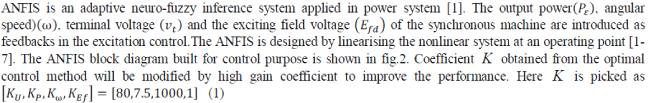
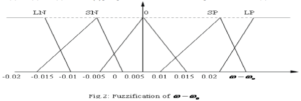
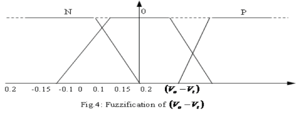
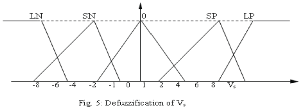
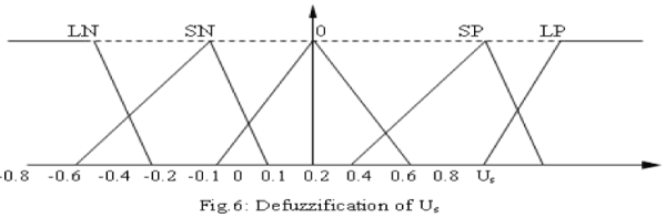
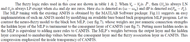
| The basic dynamic behavior of a generator can be shown using a simple single machine to infinite bus system as in fig.1. In proposed study, the control scheme was designed for the single generator [11]. The governing control is a traditional PID Control, which is similar to IEEE type 1 model. The excitation control is a CANFIS architecture. Fig.2 to fig.4 show the fuzzification of input parameters i.e. incremental angular speed(Δω),power (Pε)and terminal voltage(Vt) respectively. Similarly fig.5 & fig.6 show the output parameters, i.e. source voltage and command signal respectively [1-3]. |
 |
 |
 |
 |
 |
 |
 |
 |
 |
DESIGN OF ANFIS COMPENSATION MODEL |
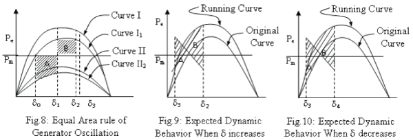
| Two performance indices (i) oscillating time or system damping should be faster, (ii) transfer capability, the more power transferred, the better are demonstrated here. In a single machine to infinite bus system, the power output of generator can be expressed as |
| When during a fault in the transmission line as shown in fig.8 the operating point will run along the curve II during the fault period. When the fault is cleared, the machine will run along the curve I. Area A is accelerating energy and B is decelerating energy. For damping A and B must be smaller. For this either the mechanical power input (Pm) is reduced or electric power output (Pε) is increased [8,12]. |
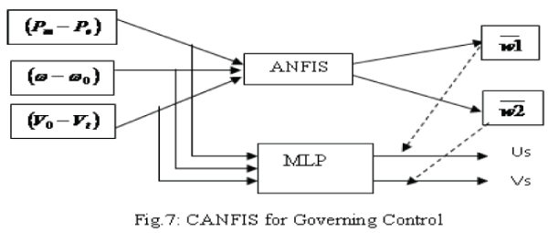
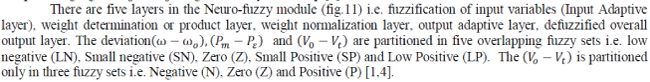
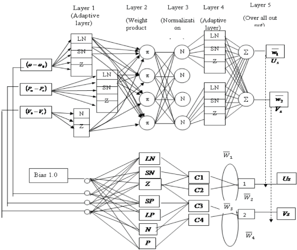
| After the first swing the same behavior is followed, increasing the voltage and decreasing the mechanical power when machine is in acceleration and decreasing the voltage and increasing the mechanical power when machine is in deceleration. These are shown in fig.9 and fig.10. Considering the slow reaction of governing system, two compensating signals Us and Vs are generated by MLP loop [1]. |
 |
 |
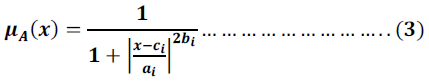
| Fig.11: CANFIS Model for Three inputs, Two outputs first-order SugenoNeuro- fuzzy model |
| Layer 1: The output of each node is: |
| So, theO1,i(x) is essentially the membership grade for x and y. |
| The membership functions could be anything but for illustration purposes we will use the bell shaped function given by: |
 |
 |
 |
| From an architectural point of view, CANFIS’s powerful capability stems from pattern-depended weights between the consequent layer and the fuzzy association layer. Membership values correspond to those dynamically changeable weights that depend on input patterns. In contrast, the back propagation MLP with sigmoid neuron functions globally updates weight co-efficient for every input pattern, attempting to find one specific set of weights common to all training patterns. Locally tuning neural networks with normalization may lead to extrapolation results comparable to the back propagation MLP. |
| A sigmoidal function is taken as a neuron function in the consequent layer. Then nonlinear consequent is given by: |
| Although the inside of each neural consequent turns out to be a black box, the whole CANFIS model restrain the concept of fuzzy reasoning in terms of the behavior of the whole system. One possible way of obtaining more precision in a given mapping is to construct the sophisticated neural consequents without increasing fuzzy rules, although commonly more membership functions or more fuzzy rules are introduced with little attention to interpretability. |
 |
SIMULATION RESULTS |
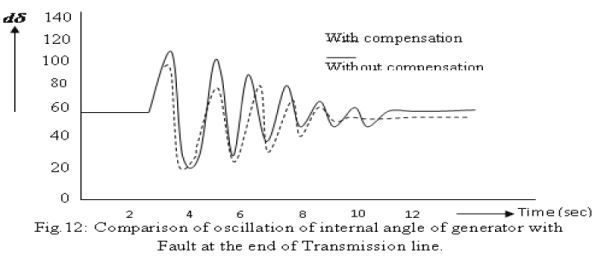
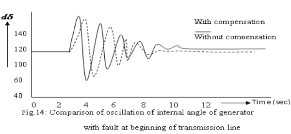
| In the simulation, the performance of the controllers with and without compensations is verified. A three phase fault is applied at t = 2.0 seconds at the beginning of one line and lasts for 0.2 second. By comparing the oscillation of internal angle δ of generator for fault at the end of transmission line in two cases, with and without fuzzy logic compensation, as shown in fig.12, the oscillation of δ in the case with compensation is damped faster then that without compensation [14] |
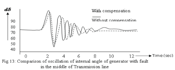
| Similarly fig.13, fig.14 and fig.15 show the comparison of oscillation of internal angle of generator with a fault applied respectively at the end, the middle, beginning and generalized form of transmission line for two cases i.e. with CANFIS compensation and without CANFIS compensation. The dotted line curve shows the response of damping without CANFIS compensation and solid curve shows the response of damping with CANFIS compensation. Also some other cases were simulated to check the performance of the proposed compensation, including the single line to ground, double line to ground and line-to-line faults. The transient amplitude of dω for the fault developed at the end of the line (fig.12) is least i.e. 60, whereas for the fault developed at the middle is higher i.e.75, but for the beginning fault location it is highest i.e. 100. Also in the fig.12, 13, and 14 the dotted line shows that the fault damping (rectification) is earlier with compensated system than without compensation. |
 |
 |
 |
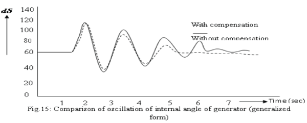 |
| The compensating signal Us for governor generated by CANFIS block and the generated compensating signal Vs for the conventional control (linear optimal excitation control) are referred as the control with CANFIS compensation and without CANFIS compensation respectively. By comparing the oscillation of internal angle δ of generator in the two cases, with and without CANFIS compensation as shown in fig.15, the oscillation of δ in the case with compensation is damped out faster than without compensation. |
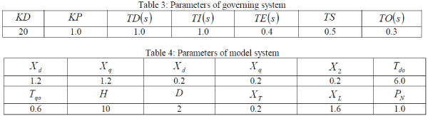
| The transient stability of single machine infinite bus (SMIB) is compared here. Three-phase fault in beginning of transmission is used as an example. Table 3 and 4 are showing the parameters of governing system and the parameters of modeled system respectively. |
| Table 5 shows about 5.2% increase of transient stability using CANFIS compensation is obtained. The benefit came from the decrease of mechanical power and increase of voltage after fault disappeared in the first swing. |
 |
| The robustness of compensated control is studied in simulation. The severe ness of system faults is simulated by the faults at different positions in the transmission line. The fault at the beginning, in the middle and at the end of transmission line is studied. It can be observed that the proposed compensation is robust in different system faults. In serious in slide system faults cases the compensation helps the original controls to damp the system oscillation. When the disturbances are trivial, which won’t cause large oscillation, as designed, there are no compensating outputs. |
| The cases with only one compensating output are also studied. When only the output for exciting control is added, the control performance is better than that without compensation except the first swing. When only the output for governing control is added the first swing is better but those after first swings are worse than the oscillation in the case without compensation. |
CONCLUSION |
| The generator controls are investigated in a single machine to infinite bus system. By analyzing the dynamic behavior of synchronous machine, two compensating variables are introduced based on the CANFIS architecture [1,14]. Since both governing and exciting controls are compensated, the proposed CANFIS compensator coordinates the behaviors of two controls. The transient stability of the transmission line also compared. |
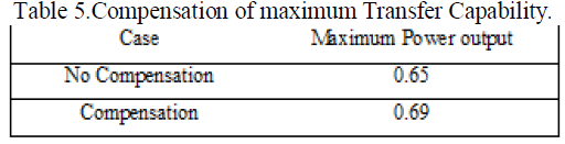 |
| Table 5 shows us about 5.2% increase of the transient stability14. The benefits came from the decrease of mechanical power and increase of the voltage after fault disappeared in first swing [1]. The robustness of the proposed control is studied .The compensated generator controls display good performance for different disturbance. |
References |
|