ISSN ONLINE(2319-8753)PRINT(2347-6710)
ISSN ONLINE(2319-8753)PRINT(2347-6710)
| Mithunkumar C.N, Venkateshmurthy Mechanical department, NMAMIT, Nitte, India. |
| Related article at Pubmed, Scholar Google |
Visit for more related articles at International Journal of Innovative Research in Science, Engineering and Technology
An Antenna is basically a dish-shaped device of parabolic design, constructed with the purpose of sending and receiving signals from Satellites, which transmit data transmissions or broadcasts, among other things. Unidirectional carbon/epoxy and glass/epoxy composite laminates are highly orthotropic, with their conductivity and permittivity being strongly dependent on the incident angle relative to the fiber orientation.This project deals with the structural analysis of the composite reflectors which is subjected to high wind loads. The displacement stress and mass of Antenna Reflector is found by varying the thickness of antenna Tress and analysing them. The Report “Design and analysis of Antenna Reflector using composite materials” presents the theoretical design calculation finite element analysis of the Antenna Reflector.it occurs load estimation design calculation and static analysis of the Antenna Reflector to determine displacement, mass and stress.The design activities involved in the Antenna Reflector are estimation of the resultant load acting on the Reflector due to wind inertia and self-weight of Antenna Reflector. Preparation of 3Dconceptual modelling using CATIA-V5, Structural Analysis of Antenna Reflector using FEA involving following steps like preprocessing/ meshing of Reflector Assembly using HYPERMESH and solution, post processing using NASTRAN and HYPERVIEW for evaluation of the stress and displacement of the Antenna Reflector Assembly was carried out.
Keywords |
| Antenna Reflector,carbon fiber, Rain forced polymer |
INTRODUCTION |
| A Cassegrain Antenna is a parabolic Antenna in which the feed antenna is mounted at or behind the surface of the concave main parabolic reflector dish and is aimed at a smaller convex secondary reflector suspended in front of the primary reflector. The beam of the Radio waves from the feed illuminates the secondary reflector, which reflects it back to the main reflector dish, which reflects if forward again to form the desired beam. The Antenna Reflector consists of the following parts: Reflector, Truss Supporting Element, and Central Drum. |
| REFLECTOR: Reflector surface provides a physical mode for the communication between satellite and ground system. It is mainly made up of aluminium with appropriate thickness based on assembly. Its function is to reflect electromagnetic waves.Various design factors have to be considered while designing the structure of a reflector. Some parameters to be considered include |
| • Spillover (part of the feed antenna radiation misses the reflector) |
| • Aperture blockage (also known as feed blockage: part of the feed energy is reflected back into the feed antenna and does not contribute to the main beam) |
| • Reflector surface deviation |
| • Defocusing |
| • Cross polarization |
| • Feed losses |
| • Antenna feed mismatch |
| • Non-uniform amplitude/phase distributions |
| REFLECTOR SUPPORT (TRUSSES): The structure that holds the reflector in place and evenly distributes the load is the reflector support, also called Backup structure. This consists of trusses of galvanized iron pipes with varying cross section and thickness. It consists of the top and bottom surface. The top structure has the same profile as that of the reflector surface. This is the functional requirement of the structure, based on assembly and manufacturing requirements. Structure consists of pipe sections and “L” angles. The pipe sections act as longitudinal stiffners and “L” minimizes the bending of interconnecting members. |
| For the utmost sturdiness and dependable performance, the trusses are mounted and fixed in proper sense with distances and angles having minimum tolerances. The backup structures are connected in proper sequence provide the necessary stiffness to the reflector. |
WIND LOAD ESTIMATION |
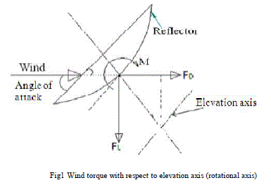
| Determination of wind pressure distribution on reflector surface of antenna plays an important role in analyzing the antenna structure. The static effect of wind is considered for calculation of forces and pressure on antenna.The antenna structure and the rest of the supporting structural systems have been analyzed and designed considering the wind loads acting at operational speed of 60kmph at any angle of attach. The wind load on the drive line varies depending upon the orientation of the reflector. |
 |
FE ANALYSIS OF ANTENNA REFLECTOR |
| Modelling of Antenna Reflector, Tress and Hub is done by using CATIA Cad software according to the dimension. |
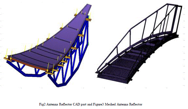 |
| Then the model which is in the Stp format is imported to hyper mesh software for Discretization process. Here we have to decide type of element for Discretization. Choosing the type of element depends on the complexity of geometry time and results (contour plot). |
 |
B. Boundary conditions: |
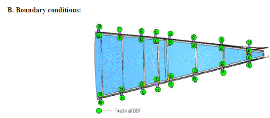 |
| Static analysis is used to determine the displacements, stresses, strains, and forces in structures or components caused by loads that do not induce significant inertia and damping effects Boundary condition involves application of load and defining constraints in the model. Rigids are applied at two sides on each clamp. Rigids applied at the clams which is shown in above figure. |
RESULTS AND DISCUSSION |
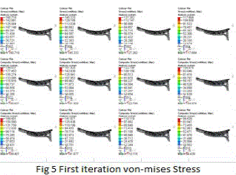 |
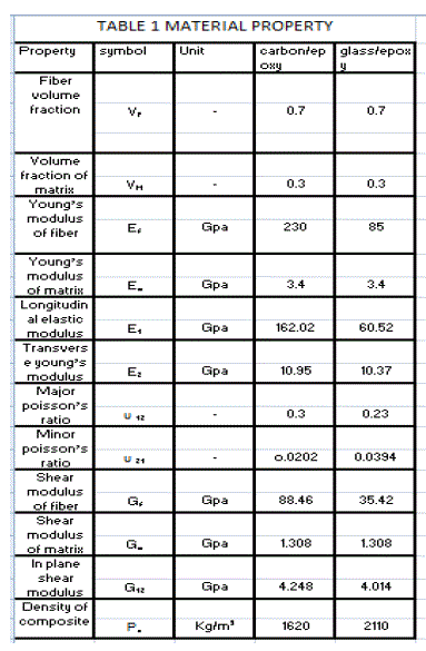
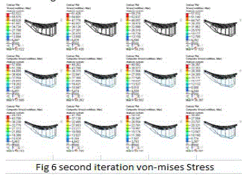
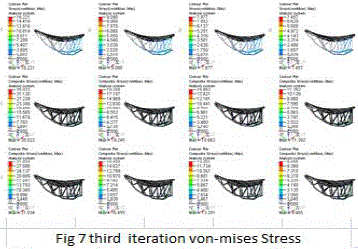
| After applying boundary condition, the file is imported to the solver. NASTRAN is used as solver here for the analysis. Finally the post-process operation (results) done by using HYPERVIEW software. In the solver we see the following results like maximum shear stress, mass von-mises stress and displacement.For a wind velocity of 60KMPH on a reflector wind load is 171.61N/M2, then for this load reaction forces obtained at the fixed point of reflector and these reaction forces are applied to the tresses for several iteration by changing design and thickness of the tresses to optimize the material of tresses by applying composite materials when compared to reference truss. Table below givens the reaction forces. Above stess resuls is for the truss design iteration 1 and varying thickness of the tress are 13, 15, 18, 20mm respectuly and also above results shows for aluminium, carbon /epoxy and glass epoxy respectuly but these iteration does not give better results. Above stress resuls is for the truss design iteration 2 and varying thickness of the tress are 13, 15, 18, 20mm respectuly and also above results shows for aluminium, carbon /epoxy and glass epoxy respectuly.The stress above results is for truss design iteration 3 which is a hollo tress in which thickness varied(3. 5, 6, 8) wch gives good displacement, stress and also mass has reduced apperciably wcich is compariable to reference tress results.Above displacement results is for truss iteration 1 and varying thickness of 13, 15 18, 20 foe aluminium, carbon/epoxy and glass/epoxy. |
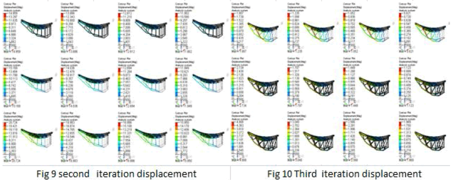 |
| Above displacement results is for truss iteration 2 and varying thickness of 13, 15 18, 20 foe aluminium, carbon/epoxy and glass/epoxy Above displacement results is for truss iteration 3 which is a hallo tress and varied thickness of 3, 5, 6and 8 for aluminium, carbon/epoxy and glass/epoxy Comaring all iterations in iteration 3 for a thickness of 5mm and for carbon/epoxy has a good stress displacement and max weight reduction. |
 |
 |
CONCLUSION |
| From the static analysis maximum von mises stress, displacements and mass for iteration 3 of thickness 5mm for carbon/epoxy is 19 ,1.7and 29.5kg respectively. Results from FE analysis is having mass less than the reference tress. In the third iteration for carbon/epoxy has a good deflection stress and mass optimized for all thickness but for a thickness of 5mm has a better results compared to all |
References |
|