International Journal of Innovative Research in Science, Engineering and Technology
ISSN ONLINE(2319-8753)PRINT(2347-6710)
ISSN ONLINE(2319-8753)PRINT(2347-6710)
|
Vinothkumar.S Assistant Professor, Department of Mechanical Engineering, VRS College of Engineering and Technology, Villupuram, Tamilnadu, India |
| Related article at Pubmed, Scholar Google |
Visit for more related articles at International Journal of Innovative Research in Science, Engineering and Technology
Micro-Electrical discharge machining (Micro-EDM) is an electro-thermal non-conventional machining process, where electrical energy is used to generate electrical spark and material removal mainly occurs due to thermal energy of the spark. However, due to complex nature of the process, it has not been fully understood. In this investigation Finite element modelling of RC-circuit Micro-EDM process has been carried out to predict the MRR using Finite element analysis software ANSYS (v.12). This model considers Capacitance, Resistance and Voltage to predict temperature distribution on the workpiece. The results have been verified with the experimental investigation performed with the pure copper as the tool electrode and AISI 304 stainless steel as the workpiece
Keywords |
| Micro-EDM, RC-Circuit, FEM. |
INTRODUCTION |
| The micro-EDM process is one of the most common techniques in micro manufacturing. As material removal is mainly based on electrical energy between tool and the workpiece, there is no contact force exerted on the workpiece, adding to the advantages of the micro-EDM in very micro scale products [1]. The material removal process in micro EDM is very stochastic in nature. It includes a combination of several disciplines such as electromagnetics, thermodynamics and hydrodynamics [2]. |
| It is almost not possible to develop a simple and comprehensive theory to explain the process nature in every detail [3, 4]. However in order to predict approximate MRR and TWR in micro-EDM we need a simple analytical model. This approximation will provide a good guidance for selecting the suitable process parameters in the machining process, which is useful in the process planning and control. This work proposes the finite element model based on the electro thermal theory to predict the MRR of the micro-crater produced from discharges of RC-circuit micro–EDM. The developed model predicts the temperature distribution using the voltage, charging time, discharging time and discharge energy. |
| In general, the EDM machining mechanism was modelled by a thermal model for single discharge. DiBitonto et al. [5] developed a point heat source model for presenting the spark on workpiece surface. In Patel et al. [6] work, the discharge power of the plasma is used as heat source between plasma and anode interface. Cylindrical plasma with variable mass model is developed by Eubank et al. [7] for sparks created by electrical discharge in liquid media. In Kansal’s study [8], two dimensional an axis symmetric model for powder mixed dielectric has been developed using finite element method. The developed model predicts first the temperature distribution in the workpiece electrode using ANSYS software and then the MRR is estimated from the temperature profiles. Theoretical findings are found compatible with the performed experimental results. Das et al. [9] developed a finite element model for a single spark by using discharge power as boundary condition. In their investigation, DEFORM software was used to solve temperature distribution problem. Yadav et al. [10] investigated the thermal strains appear after the sparks on the workpiece surface. Van Dijck and Snoeys [11] also studied the workpiece temperature distribution in EDM by using a transient thermal model on workpiece surface. Kumar [12] investigated the thermal strains and micro cracks on workpiece surface by using heat transfer by conduction. Heat losses by radiation and other forms are neglected. The energy received by the workpiece is assumed to be 17 to 20% of the discharge channel energy. Some experimental findings are compared with the theoretical ones and closer results are observed. |
| In most of the published single spark thermo-mathematical modeling studies, the authors developed the models based on transistor pulse generator micro-EDM machine parameters. In this investigation finite element modeling is developed for RC circuit pulse generator Micro-EDM machining and effect of resistance, discharging time and discharge energy on MRR theoretically investigated and validated with experimental results. |
ELECTRO THERMAL MODELLING OF MICRO EDM |
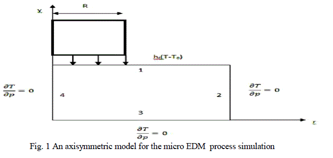
| In this paper, the analytical approach based on an electro thermal material removal mechanism is used to develop the models for anode erosion. A two-dimensional heat transfer for a material subjected to a disc heat source on its surface is used as the foundation for the model development. Empirical equations will be established to approximate the boundary conditions for determining the heat flux of anode. |
| In this study, due to the complex nature of EDM material removal process the following assumptions are made |
| 1. The ambient temperature was room temperature. |
| 2. The workpiece material was isotropic and homogenous. |
| 3. Only one spark occurs for one discharge of energy input. |
| 4. Heat transfer to the electrode surface is due to conduction and convection |
| 5. Radiation and convection heat losses are negligible. |
| 6. Two-dimensional heat transfer. |
| 7. The Gaussian heat flux is simplified by an equivalent uniform heat flux. |
| 8. Flushing efficiency is considered to be 100%. |
| 9. A constant fraction of discharge energy going to the electrodes. |
| The governing equation of the heat conduction in axisymmetric model is given in equation (1) |
 |
| Where ƞ is energy portion to the workpiece, V is the discharge voltage, C is capacitance. The energy received by the workpiece is assumed to be 17 to 20% of the discharge channel energy [12]. |
FINITE ELEMENT ANALYSIS OF DEVELOPED MICRO EDM MODEL |
| For the solution of the developed model of the micro-EDM process commercial ANSYS 12.0 software was used. |
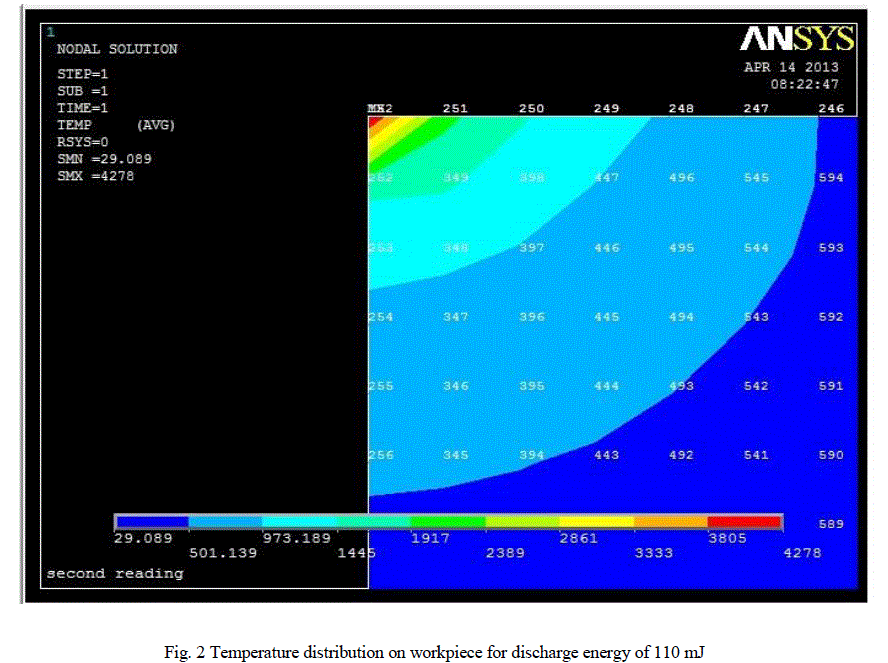 |
| From the Fig. 2 it is clear that the temperature range of green region is more than melting temperature of AISI 304 stainless steel material. Hence, when the dielectric medium is flushed, the material in the region with above melting temperature will be removed. This forms the crater and thus material removal is occurs in the micro EDM process. The radius of the crater is measured from centre node to node number 251. Thus the radius of crater is calculated for all energies. |
MATERIAL REMOVAL VOLUME FOR SINGLE AND MULTIPLE DISCHARGE |
| From the Fig.2 it is also clear that the shape of molten material is semi sphere. The molten crater can be assumed to be hemispherical in nature with a radius r which forms due to a single pulse or spark. Hence material removal volume in a single spark can be expressed as |
 |
EXPERIMENTAL ANALYSIS |
| To validate the model, it was run with chosen parameter values and the results obtained were subsequently compared with experimentally obtained data. First, we take a look at the experimentation. |
| Experimental analysis of micro EDM has been carried out using AISI 304 stainless steel as workpiece and copper as tool electrode in Multipurpose Micro machine. The specification of machine is given in Table 2. |
 |
| From the Table 3 it is clear that MRR increases with increasing discharge energy. But at discharge energy 120 mJ the observed MRR is comparatively less than MRR of 110 mJ. This occurs due to the short circuits at higher discharge energy. |
MODEL VALIDATION |
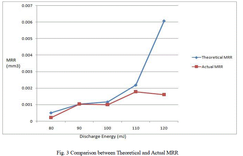
| The MRR values were calculated on the basis of material removal by melting and evaporation separately by the Finite Element Modelling using ANSYS software compared with experimentally obtained values. Fig. 3 shows the results. |
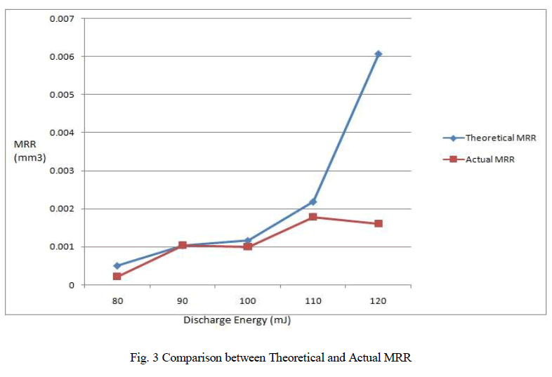 |
| The value of simulated MRR is higher than the experimental one. The main reason is that the value of simulated MRR is simply calculated by considering the molten material ejected from the surface at the end of the pulse duration but in actual process part of molten material deposited as recast layer. Another reason is short circuiting time is not considered in the modelling. From fig 3 it is clear that the model closely follows the actual process up to discharge energy 100 mJ. For higher energy level the model deviates because non linear nature of material comes into process, but this model only considers the linear material properties. |
CONCLUSION |
| For the micro-EDM process, an anode erosion model has been presented which captures the dominant physical effects. The model can be used to find the temperature variation in the workpiece as well as evaluate material removal rates under various machining conditions. This can be used as a useful methodology to set the machining parameters and achieve the desired accuracy and precision in the manufacture of components by RC circuit micro-EDM. |
References |
|