International Journal of Innovative Research in Science, Engineering and Technology
ISSN ONLINE(2319-8753)PRINT(2347-6710)
ISSN ONLINE(2319-8753)PRINT(2347-6710)
Mahantesh. HM1 and Prof. Anand. SN2
|
| Related article at Pubmed, Scholar Google |
Visit for more related articles at International Journal of Innovative Research in Science, Engineering and Technology
Investigation of airflow field over aerofoil wing is very essential to understand the flow complexity and its behaviour. In order to reduce the drag forces to achieve better performance with less power consumption for NACA 2415 model is been selected which is newly developed aerofoil wing. Drag force’s are very critical parameters to optimize the performance for various AOA’s. To understand flow complexity and how to reduce the fluid force parameters with the help of vortex generator kind of devices. Vortex Generators are highly efficient aerodynamic devices that are used widely in both external and internal aerodynamics as means of flow control. The paper deals with the CFD analysis of flow over wing at different flow regimes and as well different AOA’s without & VGs are placed on a wing. Complete three dimensional results are for the flow over wing equipped with Vortex Generators with various shapes and locations over the wing. The drag and lift characteristics of each shape and locations of VG’s have to be studied. The analyses has carried out for subsonic (M=0.5), transonic (M=1.0) and supersonic (M=2.0) flow regimes. The best shape and location of the VG’s for each of the flow regimes will be determined. All computations will be carried out using the RANS modelling which is available in commercially CFD package.
Keywords |
| Energy, temperature, computational fluid dynamics, aerofoil, wing, heat transfer, turbulence, aerodynamics. |
INTRODUCTION |
| Flow separation occurs in various flow conditions and at various locations around an aircraft, especially flow separation over the wing is of serious concern as it directly affects the aircraft performance. The oldest and the simplest mean of flow control for separated areas is using mechanical devices called vortex generators (VGs). These devices are made up of “simple” sheet metal plates which are placed at upstream of the separated area with a predetermined cross angle with the flow. The VGs create vortices, transferring momentum from the outer region of the boundary layer into the inner flow region thereby increasing the kinetic energy of the boundary layer as well as its ability to resist to adverse pressure gradient which results in sustain the flow separations. CFD in now being used extensively in the aerodynamic design and performance analysis using these VG’s on aircraft wing which be computed with reasonable accuracy. The studies have been carried out on two different VG geometries i.e. trapezoidal shaped configurations. |
Materials: |
| Aerofoil wing material is Carbon Fiber and its thermal properties are generated. Wing and Vertex Generators devices are associated with adiabatic walls |
Methodology |
| The aim of present work is to understand the flow behaviour around aerofoil wing, estimate drag force and its coefficients for different angle of attacks with different Mach. NACA-2415 model has selected for fluid dynamics study and also estimated the drag force, have a clear picture of reduction of drag force by adding additional device like a vertex generators. This is done numerical simulation method done by external aerodynamics regime with supersonic flow condition. Flow field computed and mapped by computationally using commercially available CFD tool, ICEM CFD and CFX. |
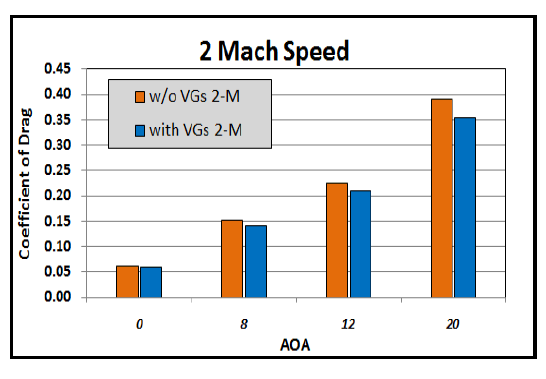
| VGs are very efficient devices to reduce the drag force, which is very good sign where energy consumption can be reduced through this kind of devices. Recent days energy consumption is increasing while increase of aero vehicles requirement for domestic and armed forces purpose. Saving energy is the key issue to increase the performance to the cost ratio optimistically. In this document drag force and its coefficients are established without and with VGs, there is very much scope in optimization of size with various simple shapes to further optimization of drag force coefficients. |
| Paper is organized as follows. Section II describes the computational model for aerofoil wing. The problem statement for flow field and drag for aerofoil is given in Section III. Section IV presents CFD results showing the simulation results using CFD software. Finally, Section V presents conclusion. |
COMPUTATIONAL MODEL |
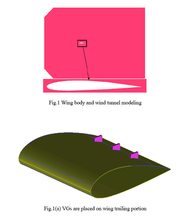
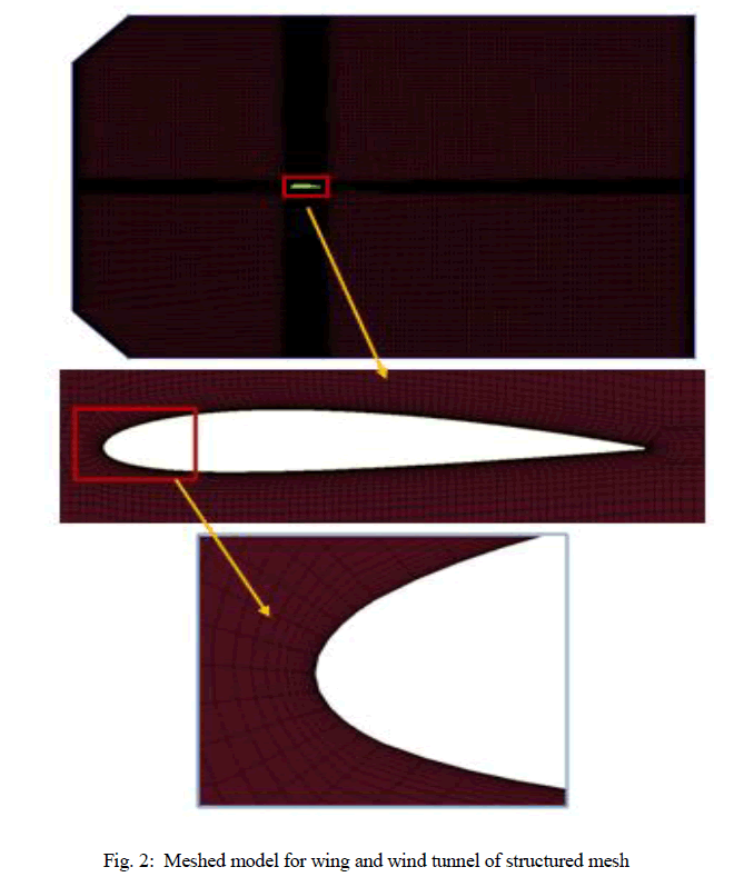
| The geometrical and fluid domain details of all the test in CFD cases that have been considered for studies are discussed in this section. It is necessary to have enough details of geometry of any test case for the purpose of modeling it on digital computer. Fluid domain is a virtually cut portion of the whole system whose outer boundaries are decided in such a way that the physics of the problem do not get affected. In all the present case studies, computational domain is the fluid surrounding the geometry (external flow problems). It is usual practice to go up to 5-8 times the width or base diameter of the body in the far field regions and 3 times in the upstream region for shock capturing problems. It is necessary to have enough details of geometry of any test case for the purpose of modeling it on digital computer. Fluid domain is a virtually cut portion of the whole system whose outer boundaries are decided in such a way that the physics of the problem do not get affected. In all the present case studies, computational domain is the fluid surrounding the geometry (external flow problems). It should be noted that, only the fluid domain is being modeled and not the solid body, since all the present case studies are being external flow problems. The models considered in the present case studies are symmetric. For both the cases (without VG’s and with VG’s) the wing body is modeled for flow at zero angles of attack. |
| 2-D geometry of wing body has been built by using ICEM CFD industrial standard code and which is shown in Fig 1. Geometrical information of wing body without VGs and with VGs configurations has been shown in Fig 2. |
 |
 |
PROBLEM STATEMENT |
| The governing equations must be satisfied in the interior of the fluid and the specific solutions can be obtained only by prescribing the constraint of flow geometry as well as the initial state of the flow field. Hence on the boundary of the region velocity, pressure and temperature must be suitably defined to permit integration of the governing equations. In the transient problems, the time derivative is of first order and the value of dependent variable at time t=0 must be given. This is called as initial condition. Other conditions prescribed on the physical boundary of the fluid region are called Boundary conditions. However, in the present problem, steady state has been assumed and hence no initial conditions have been applied. Inlet, typical values used here are velocity, pressure and temperature, these are the ambient atmospheric conditions at an above the sea level. Opening,it Open to ambient. Outlet,At the outlet of the computational domain, all variables are extrapolated from the interior domain. Wall,on the solid surface of the blunt body, the fluid is assumed to stick to the wall by the action of viscosity. This is called as no-slip condition and it requires that the solid and adjacent fluid do not have a velocity relative to each other. Hence the wall boundary condition is used at the blunt cone model surfaces and the fluid at these surfaces is assumed to have no-slip condition. |
CFD RESULTS |
| Below figure shows the different variables contours for 0 deg AOA and for without VGs and with VGs designs. 2 Mach speed flow over wing is considered to analyse the flow behaviour. The pressure and velocity contours it can be seen that the body fitted shock has been developed strongly and it is attached to the leading edge of wing. Shock waves are symmetry in the case of non zero angles of attacks. Fig 3 shows the velocity contours plots for 0 deg AOA’s at 2 Mach speed. Similarly pressure and temperature and density changes at different locations with contours plots shows in Fig. 1 to Fig. 4 which represents the without VGs and flow over wing structure. Fig. 5 to Fig. 8 represents the fluid variables for with VGs design. Below figure shows the different variables contours for 0 deg AOA. Shock waves are captured accurately and the fluid behaviour is changing due to compressible effect in leading edge of wing. |
Flow patterns over wing |
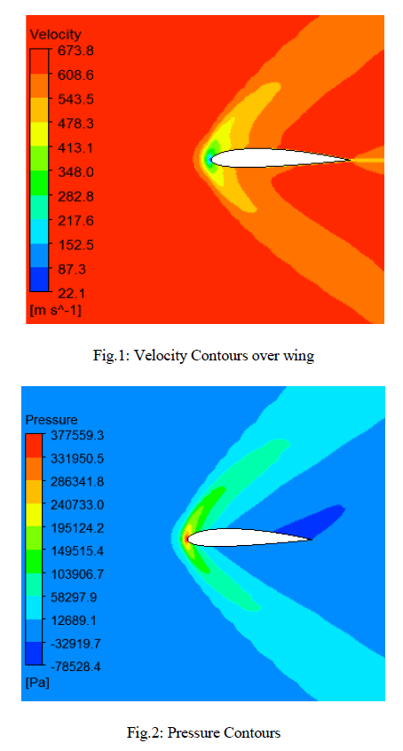 |
| The Fig.1 analysis the velocity variations for aerofoil wing at different areas and Fig.2 represents the pressure contours on aerofoil wing at different areas. |
| The colours in the figure 1and 2 represents the maximum and minimum velocity and pressure respectively. |
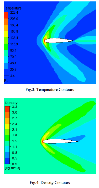 |
| The Fig.3 analysis the temperature contours for aerofoil wing at different areas and Fig.4 represents the density contours on aerofoil wing at different areas. |
| The colours in the figure 3and 4 represents the maximum and minimum temperature and density respectively. |
Flow patterns over wing with VGs |
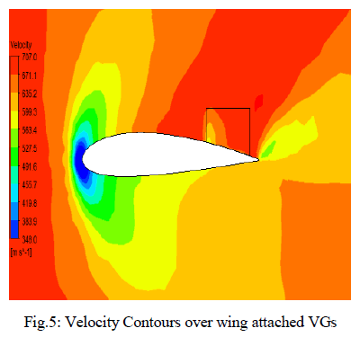 |
| The Fig.5 represents the velocity contours over wing attached in Vertical generators. |
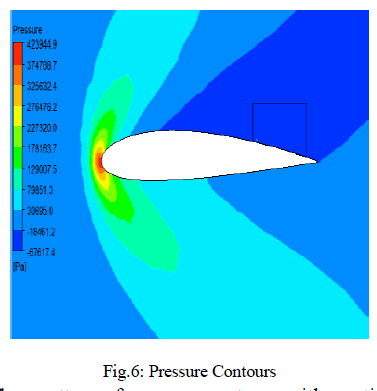 |
| The Fig. 6 represents the analysis of flow pattern of pressure contours with vertical generators over the wing. |
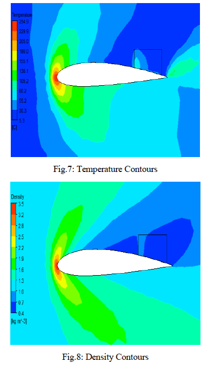 |
| The Fig. 7and 8 represents the analysis of flow pattern of temperature contours and density contours with vertical generators over the wing. |
CONCLUSION |
| VGs are very efficient devices to reduce the drag force and its coefficients, in this study one can able see the difference of flow patterns with and without VGs. Drag coefficients are reduced almost 6% for all different AOA as compare against without VGs in place, which is very good sign where energy consumption can optimized through this kind of devices. |
 |
References |
|