International Journal of Innovative Research in Science, Engineering and Technology
ISSN ONLINE(2319-8753)PRINT(2347-6710)
ISSN ONLINE(2319-8753)PRINT(2347-6710)
| Abhishek Gupta1 & Amit Dhir2 Assistant Professor, Department of Environmental Science and Engineering, Marwadi Education Foundation’s Group of Institutes, Rajkot, Gujarat, India1 Assistant Professor, School of Energy and Environment, Thapar University, Patiala, Punjab, India2 |
| Related article at Pubmed, Scholar Google |
Visit for more related articles at International Journal of Innovative Research in Science, Engineering and Technology
This paper presents estimation of horizontal pollution potential due to an air pollution source using impact area diagrams. Weather monitoring station was installed at an altitude of 10 m from the ground to collect wind data of Patiala in Punjab province of India. The data was collected for the period commencing from October, 2010 to September, 2011 with an interval of 1 h which was further grouped into seven wind speed ranges. Change in wind direction rotates the impact distance that has been approximated using standard deviation of change in wind direction. Standard deviation was calculated using Yamartino method and thus, impact area has been calculated. The experimental data reveals that 50% of the wind speed data comes under calm period due to extremely low wind velocities. The maximum impact area noticed was 41 m2 in the month of November 2010 and 21m2 in the month of February as well as March, 2011. Impact area was predominant towards east direction for whole of the study period. Worst condition of pollution was observed in the month of June as impact area was minimal. In general, the horizontal pollution potential of the area has been found to be low for most of the study period, thus resulting in high concentration of pollutants adjoining the source.
Keywords |
| Impact area diagram; Yamartino method; Standard deviation; Wind rose diagram. |
INTRODUCTION |
| Air pollution is one of the areas of environment which needs immediate attention. India being a developing country two major sources of air pollution namely automobile exhaust and industrial emissions. The level of air pollution is getting worse because of rapid industrialization, growing number of vehicles, energy consumption, and burning of wastes. So to keep an eye on the existing air environment, air quality monitoring programs and environmental impact assessments were initiated. All programs differ in selection of pollutants to be monitored, duration as well as frequency of monitoring and site selection criteria. Positions of source and wind data are important parameters which plays a vital role in studying the impact area. Wind is a vector quantity having both magnitude and three-dimensional direction. This makes wind a spherical variable. However, only the horizontal component is considered in this study. Thus, wind is mainly treated as a circular variable with an associated magnitude. Wind data having speed and direction can be represented as wind rose diagram, first done by Leon Lalanne of France in 1843 [5]. In this length of arm represents the frequency of a specific wind direction and its position on polar coordinate represent wind direction. Number of arms can be decided by user, 4, 8, 16 and maximum of 360. In wind rose, a small circle at centre represents calm period where wind speed is less than 1km/hr. Impact area diagrams are used to represent affected area by an air polluting source. If centre of the circle of the diagram is placed on the source of air pollution and its direction is oriented according to the source geographical direction then the diagram can represent the maximum affected area and its direction. |
| Traditional or linear Statistics are available for linear variable like age; length etc as they are continuous variable so can be plotted onto real number line [4]. Their mean, median and standard deviation can be calculated by using well defined equations but it is not same for periodic variables that starts from 0 to a certain point and repeat itself, like wind direction. Such periodic variables needed to be plotted on a circle not on a number line. That’s why mean and standard deviation of horizontal wind direction is a long standing problem. But standard deviation (So) is a very important quantity in meteorology and climatology because of its link to lateral turbulent intensity iv [7], defined by following equation |
| Tan (So) = iv |
| and lateral spread of a plume is given by following equation |
| Slat = tan (So) × f(x) |
| Which, reduces to Slat = So × f(x) for very small So. Aerodynamics resistance and quasi-laminar boundary layer resistance can also be calculated using wind standard deviations which are needed to calculate deposition velocity of particles [8]. |
| A number of equations have been proposed and compared to calculate the standard deviation of angular dispersion ([1], [2], [10], [12]-[18]). But the equation given by reference [2] and reference [18] are two most accepted equations to calculate standard deviation. However, a direct mathematic analysis to establish a relation between the two equations has not been carried out. The single pass method was used to calculate the standard deviation ([18], [11]). Earlier studies for the estimation of impact area have been reported by calculating standard deviation using wind direction persistence ([6], [9]), however the present study focuses on standard deviation calculation by Yamartino method which has been applied to a city in northern India. |
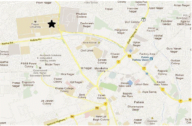 |
| Fig. 1 Site selected for data collection |
II. MATERIALS AND METHODS |
| A. Instrument Used |
| Watch dog instrument has been used for weather monitoring which uses different sensors to monitor seven parameters including wind speed, wind direction, temperature, relative humidity, dew point, pressure, solar radiations etc. Lightweight three cup anemometer has been used for measuring wind speed ranging from 0 to 175 mph and wind vane is used for the determination of wind direction. Data logger allows storage of data for 6 months at a time and the stored data can be transferred to computer using data cable. The weather monitoring station used in this study was Watch Dog of Spectrum Series 2000. SpecWare 6 software was used to handle data logger and also for data extraction from it. SpecWare can present data in graphical and tabular form. |
| B. Site Selection |
| Weather monitoring station was placed within campus of Thapar University (30°35'39"N, 76°37'07"E), Patiala city located in south-eastern Punjab, India. It was located at height of 10m in an open area. This height was chosen to neglect effects of terrain and nearby buildings on wind speed and direction. The study area is shown in Fig 1 and site of instrument placed to collect wind data is marked with star mark. Topography of site is a broad and relatively flat plain, at an average elevation of 250 meters (820 feet), and the climatic condition in Patiala is tropical and dry. Monsoons in the city of Patiala are moderate and extend through the months of July, August, September and early October. Wind data has been collected at an interval of 1hr for one year starting from October, 2010 to September, 2011. |
| C. Methodology |
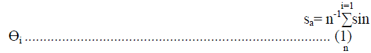
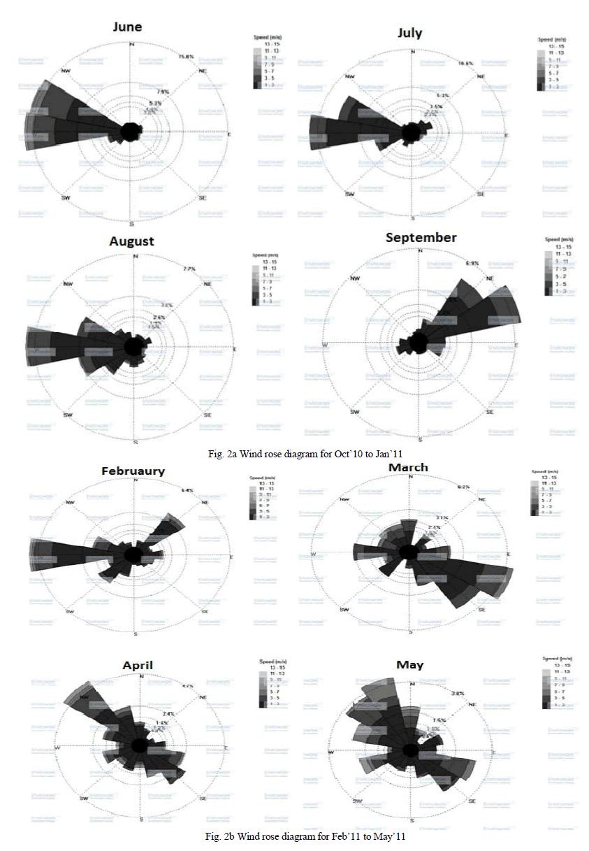
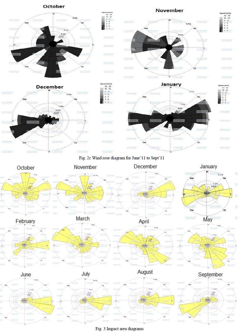
| The study was carried out in three steps viz. constructing of wind rose diagrams, impact area diagrams and determination of impact area [9]. In first step, wind roses were constructed from the data collected for wind speed and direction. Each concentric circle represents a different frequency, emanating from zero at the center to increasing frequencies at the outer circles. Using a polar coordinate system of gridding, the frequency of winds over a long time period were plotted by wind direction, with colour bands showing wind ranges. In order to plot wind rose diagram, seven different wind speed ranges were taken into consideration. The direction of the wind rose with the longest spoke shows the wind direction with maximum frequency. Wind rose diagram have been plotted using Wind rose pro setup from Enviroware. Calm period was taken for speed range <1kph and it was included at the centre of the diagram. After plotting wind roses, impact area diagram were constructed using methodology given in reference [6]. Impact area diagrams were drawn by superimposing all the sector area over one center having arc radius equal to the average wind speed [6]. Impact area diagrams are helpful, in obtaining the idea about most affected wind direction from the source. In the final step, wind data were grouped into different category of wind speed, and for each wind speed category, the average distance travelled by the pollutant per unit time from the source can be represented by the mean wind speed (Vj) of that category. For example, wind speed category can be taken from 1 to 3, 3 to 5, 5 to 7 and 7 to 9 kmh−1 etc. For calculating standard deviation, wind speeds more than 1 kmh−1 were taken into consideration excluding calm wind conditions. Impact area under different wind speed categories were summed up to obtain the total impact area [6]. Since different wind speed groups may indicate different direction of impact area, its linear summation was weighted by persistence of impact area, thereby yielding dilution potential. The standard deviation (σÃâ ß) of the wind direction is estimated from Yamartino method. First of all, average of sine and cosine of wind direction angle was calculated using equation 1 and 2 for each specific wind speed class. Then these average values were used to calculate average wind direction for that specific wind speed class [3]. |
 |
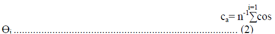 |
| Average wind direction was calculated using the four-quadrant arctan(x,y) function as mentioned in equation 3. Values of ca and sa were taken without any positive and negative sign. |
| But values obtained from above equation needs correction as sign of ca and sa are neglected in above formula. So to calculate final average wind directions following condition was used. |
| Ãâ ß= If sa<0 & ca<0 then 180+Ãâ ß |
| If sa>0 & ca<0 then 180-Ãâ ß |
| If sa>0 & ca>0 then Ãâ ß |
| If sa<0 & ca>0 then 360-Ãâ ß |
| Consider an example that if value obtained for Ãâ ß is 60o from equation 3, with value of ca with negative and sa with positive sign, means final value of Ãâ ß will lie in 2nd quadrant. This is due to the fact that in 2nd quadrant, sine function has positive value and cosine function has negative value. Then the final value taken for Ãâ ß is 120o i.e. by applying 2nd condition by which 180o-60o=120o is the final value for Ãâ ß. For the calculation of standard deviation, first Ãâàis calculated using values of sa and ca using following equation. This value of Ãâàis then used to estimate the value of standard deviation which can be obtained by using equation 4. |
 |
| Where, |
| ÃâÃÂ= [1-(sa 2+ca 2)]1/2 |
| Mean wind speed was calculated by just taking average of all the value of wind speed obtained with in a specific wind speed class. Impact area [6] can be calculated by using equation 5. |
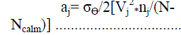 |
| where, σÃâ ß = angular standard deviation of the specific group; |
| Vj |
| 2 = mean wind speed for the specific group; |
| nj = number of wind data in specific wind speed category; |
| Ncalm= number of wind data in calm period range (<1 kmh−1) and |
| N = total number of wind data. |
| Values for standard deviation, mean wind direction calculated earlier were used to calculate impact area. |
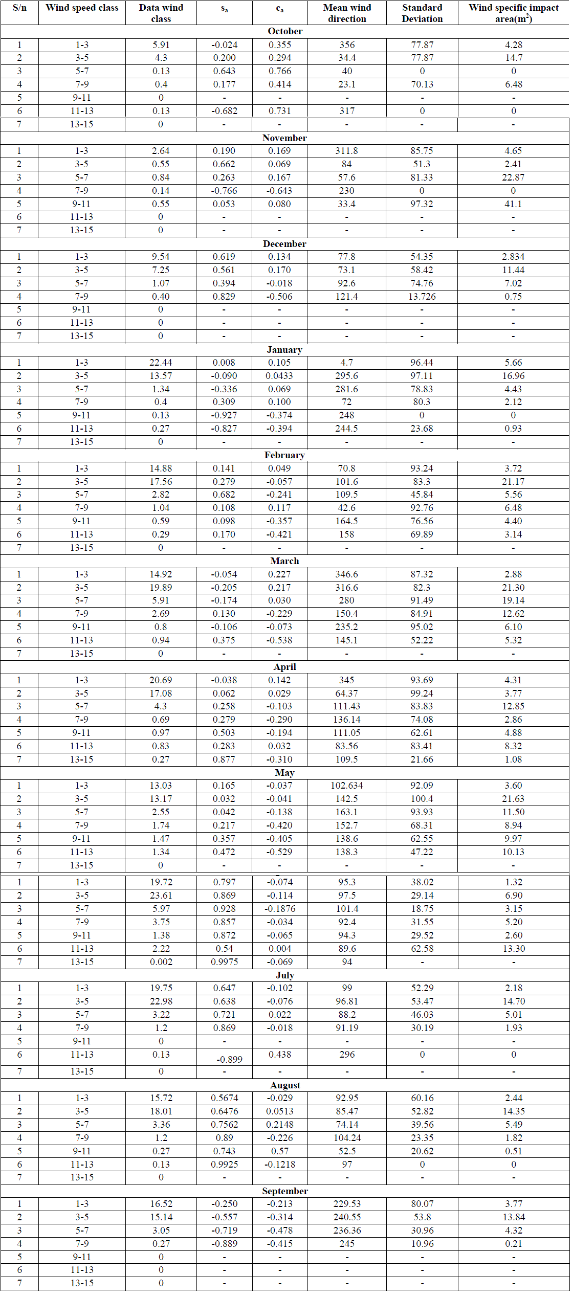 |
| Table I Calculated Values for Standard Deviation and Impact Area. |
 |
 |
III. RESULT AND DISCUSSION |
| Wind data collected at mentioned site has been analyzed by the methodology as discussed in section 2. Wind data was collected at an interval of 1 hr for the study period of twelve months. Conventional wind rose diagrams were plotted for the wind data and are presented in Figs. 2a, 2b and 2c. The conventional wind rose diagram can only depict wind frequencies from different directions at a location but it does not give a pictorial view of the downwind distance up to which wind can cause pollutant to travel. Using above estimates, wind impact area diagram have been plotted and are presented in Fig. 3. However, if the center of wind impact area diagram is superimposed over a ground level pollution source, the downwind distance up to which pollution can travel can be gauged and accordingly the sampling location can be fixed. Wind speeds were grouped into seven categories and standard deviations of the wind direction and impact area were determined. These calculated values of standard deviation and impact area are given in Table 1. It can be inferred from Figs. 2a, 2b and 2c, that the maximum frequency of wind speed comes under calm period due to extremely low wind velocities i.e. <1 kmh−1 with predominant wind direction towards West (winds blowing from East to West), resulting in impact area towards the East direction. Comparatively high wind speed had been seen during summer season than that of the winter season. In the first quarter (October to December, 2010), 80% of wind data collected comes under calm period as shown in Fig. 2a with angular standard deviation of wind direction to be between 70o-80o. 95.3% of the total wind speed measurements reading taken during November, 2010 come under calm period. Because of this reason, dilution potential of the pollutant is least. In month of December, 2010 predominant wind direction is West-West-South. In the month of January, 2011 nearly 62% of wind data collected comes under calm period. Where as in months of February to May, 55-66% comes under calm period. In month of April and May, heavy winds of greater than 11 km/hr were noticed, as shown in Fig. 2b. Fig. 2c depicts that predominant wind direction was towards west during the study period from June to August, 2011. In June, 43% of total data comes under calm period whereas in other months it was in range of 53 - 65%. Table 1 shows that maximum impact area achieved was 41 m2 in month of November, 2010 with mean direction of 33o i.e. towards North-West direction whereas in month of October and December, 2010; impact area remained concentrated as the value was less than 14m2. During second quarter (January to March, 2011), maximum impact area was 22m2 with wind direction towards West in month of January and March but towards east in the month of February (Fig. 3). In the months of March, April & May, 2011; the wind remained distributed among all directions; mainly the wind direction was North-West and South-East. In April and May, impact area was towards South-East. In the last quarter varying from July to September, 2011; maximum impact area was found to be 14m2. The impact was observed to be toward East direction of the source in July and August but in September the direction was found to be West. Worst condition of pollution was observed in the period from June to August, as impact area was maximum towards the East direction of the adjoining areas. Almost for the whole month the pollutant spread was found in the East of the source and therefore air monitoring sampler can be placed in East direction to the source. |
IV. CONCLUSION |
| Wind data plotted in form of wind rose diagrams is of interest to the town planners as well as environmental scientist while, the impact area diagrams are the tools for the prediction of the direction in which the pollutants would travel under the influence of wind. Continuous weather monitoring study of one year in the area reveals that 50% of the wind speed data comes under calm period and maximum wind speed of 14.5 km/h was observed in the month of April, 2011. Out of total wind data, only 12% resulted in impact area of more than 10 m2, which may be responsible for high concentration of pollutants within the specified area. Further, periods of air pollutant sampling can be selected by comparing total impact area for different months of the study period. Through this impact area calculation, it has been observed that the horizontal pollution potential is less for majority of the study period hence; establishments of large number of industries near the monitoring site cannot be recommended. |
ACKNOWLEDGEMENT |
| I express my sincere gratitude and regards to my supervisor Mr. Amit Dhir, Assistant Professor, School of Energy and Environment, Thapar University, Patiala for his valuable guidance and suggestions. |
References |
|