ISSN ONLINE(2319-8753)PRINT(2347-6710)
ISSN ONLINE(2319-8753)PRINT(2347-6710)
Kathirvel . M1,.Sundaram. G 2
|
| Related article at Pubmed, Scholar Google |
Visit for more related articles at International Journal of Innovative Research in Science, Engineering and Technology
Nowadays, demands for developing metal matrix composites for use in high performance applications, have been significantly increased. Among these composites, aluminum alloy matrix composites attract much attention due to their lightness, high thermal conductivity, moderate casting temperature, etc. Various kinds of ceramic materials, e.g. SiC, Al2O3, MgO and B4C, are extensively used to reinforce aluminum alloy matrices. In this project Aluminium Alloy (LM4) is reinforced with 1, 1.5, 2.5 and 5% of nano particle of Aluminium oxide (Al2O3) and fabricated by using stir casting method. The fabricated Aluminium oxide (Al-Al2O3) nanocomposite materials are tested using tensile and hardness testing machines to determine its Mechanical properties. And the results are compared for choosing the best composite .A microstructure test was also conducted to determine the best results. Finally the composites are analyzed using Ansys version 10.0 Software.
INTRODUCTION |
| OVERVIEW: |
| A Liquid rocket engines employ liquid propellants which are fed under pressure from tanks into a combustion chamber. In the combustion the propellants chemically react (burn) to form hot gases which are then accelerated and ejected at high velocity through a nozzle, there by imparting momentum to the engine. Momentum is the product of mass and velocity. A thrust force of a rocket motor is the reaction experienced by the motor structure due to ejection to the high velocity. |
| According to the Newton’s third law: |
| “For every action there is an equal and opposite reaction” |
| Based upon this law only the rocket works |
| Nozzle: |
| The function of nozzle is to convert the chemical - thermal energy generated in the combustion chamber into kinetic energy. The nozzle converts the slow moving, high pressure, high temperature gas in the combustion chamber into high velocity gas of low pressure and temperature. The nozzle is usually made a long enough (or the exit area is greater enough) such that the pressure in the combustion is reduced at the nozzle exit to the pressure existing outside the nozzle. If the rocket engine is being fired at sea level this pressure is about 14.7 Psi. If the engine is designed for the operation at high altitude the exit pressure is less than 14.7psi. The drop in the temperature of the combustion gases flowing through nozzles is high and can be as much as 2000-3000F. Since the gases in the combustion chamber may be at 5000-6000F. The gas temperature at the nozzle exit is still about 3000F. |
| DE-LAVAL (CONVERGENT &DIVERGENT): |
| A Rocket engine nozzle is a propelling nozzle usually of the DE-LAVAL type used in a rocket engine to expand and accelerate the combustion gases, from the burning propellants, so that the exhaust gases exit the nozzle at the supersonic velocities. |
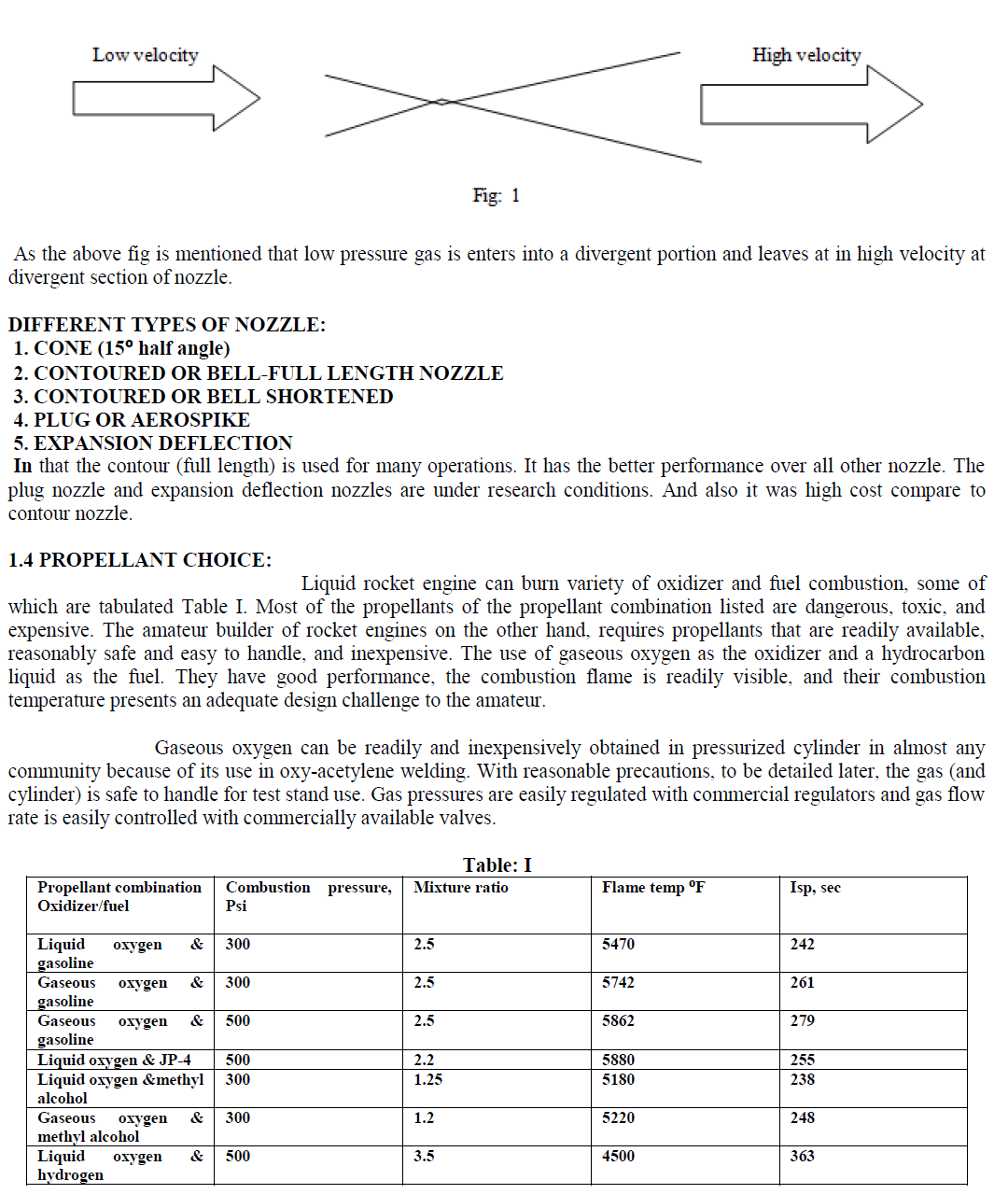 |
| From the tables we can observe that Liquid oxygen & hydrogen is with standard high temperature and pressure. |
LITERATURE REVIEW |
| 1. Scott Forde .et.al. Has discussed that larger area ratio nozzle produces less thrust. The main chamber should be operated at constant pressure. By adding TAN specific-pumps would separate engine and TAN development. And most important benefit of TAN is increases engine system reliabilities resulting from operating the engine at chamber Pressure below the structural Design condition. And carried a two –hot fire tests on the TAN concept. The first tests were performed with single propellant injection into a 2000-lbf-thrust GOX/gases hydrogen rocket engine. Over 40% increase in sea-level thrust using a 25:1 expansion area ratio nozzle. The second tests carried by adding a water-cooled chamber. The TAN injector at 2:1 into a water-cooled nozzle [1]. |
| 2. Taro Shimizu.et.al. This study says that how the flow structures inside and outside a rocket nozzle. Due to over pressure which originates in shock waves, and improves high pressure load on the nozzle (or) rocket surface. Under clustering nozzle configuration, the interaction between the nozzles. As the NPR increases the overpressure arrives at the nozzle tip decreasing its amplitude. The function positive (or) negative based upon the pressure increases (or) decreases along the stream line. Due to clustering of nozzles the pressure disturbance induced by the neighbouring nozzle is 10% of the atmosphere pressure. The transition of the flow structure between free shock separation and restricted shock separation inside a nozzle, which would sometimes generate a destructive side-load[2] |
| 3. Macro Geron, et.al. This work investigated the three –dimensional flow generated on this partitioning the primary nozzle into modules. A linear plug nozzle has been together with modules having two different geometries: rectangular cross section and Round –to-square module. The flow field of the test case R2S appears richer in the three dimensional effects than the test case REC. losses are happened due to the adjacent modules. The viscous stresses are high at nozzle exit. The gap is increased the plug contribution affected less. The partitioning of the primary nozzle with round-to-square modules causes a thrust reduction with respect to the two-dimensional model which can exceed1%. This paper says that to improve module efficiency and to reduce the maximum mechanical and thermal stresses[3] |
| 4. Lunciano Garelli et.al. He analyzed the aero elastic process developed during the starting phase of a rocket engine. Better understanding of the behaviour of the structures as the shock waves propagate inside the engine nozzle. During the start up-phase the structure is deformed due to the advance shock wave that is highly detrimental to service life cycle of the rocket engine. Design of a nozzle it is important to predict the response of the structure under the thrust loads[4] |
| 5. Guobiao Cai, et.al. He was optimized the liquid rocket engine nozzle using the CFD method. For solving the two-dimensional axis symmetric Navier- strokes equation (NS) and transport equations in an efficient number. this optimization is generates nearly 1.5% performance improvement over the initial one, approximately half of which is attributed to the decrease of friction loss, and the other half to the decrease of axial loss[5] |
METHODOLOGY |
 |
| Ae Area at exit condition |
| In the above equation says that the Thrust can be increased by mass flow rate of the propellant (Ma) (or) increasing the exit velocity (Ve) (or) increases the exit area (Ae). Here the mass flow rate depends upon the propellant mixture ratio and also it will produce a large thermal stresses on the walls of the nozzle. And the velocity is depends upon the pressure condition. And by increasing the area we can improve the Thrust of the rocket engine. |
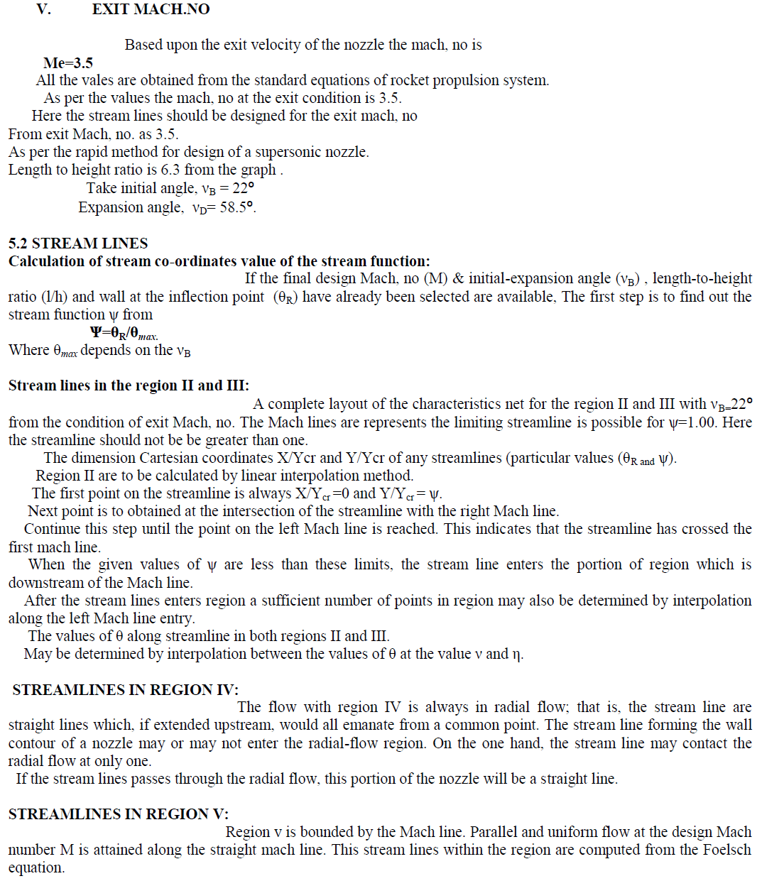
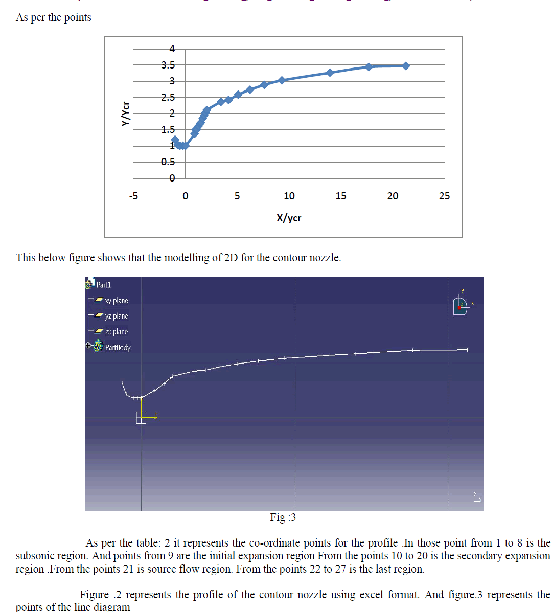
| Area be modified by changing the exit dia of the nozzle with the exit Mach.no.and profile curve of the nozzle. Based upon the streamlines and the co-ordinate points of the nozzle profile curve may be obtained. The best method is for the nozzle contour shape it gives the best performance |
AN ACCURATE AND RAPID METHOD FOR THE DESIGN OF SUPERSONIC NOZZLE |
| OVERVIEW: |
| This method is simple in all other methods. It gives the accurate and easy calculation of the nozzle contour from the derived equations of the stream lines flow region. |
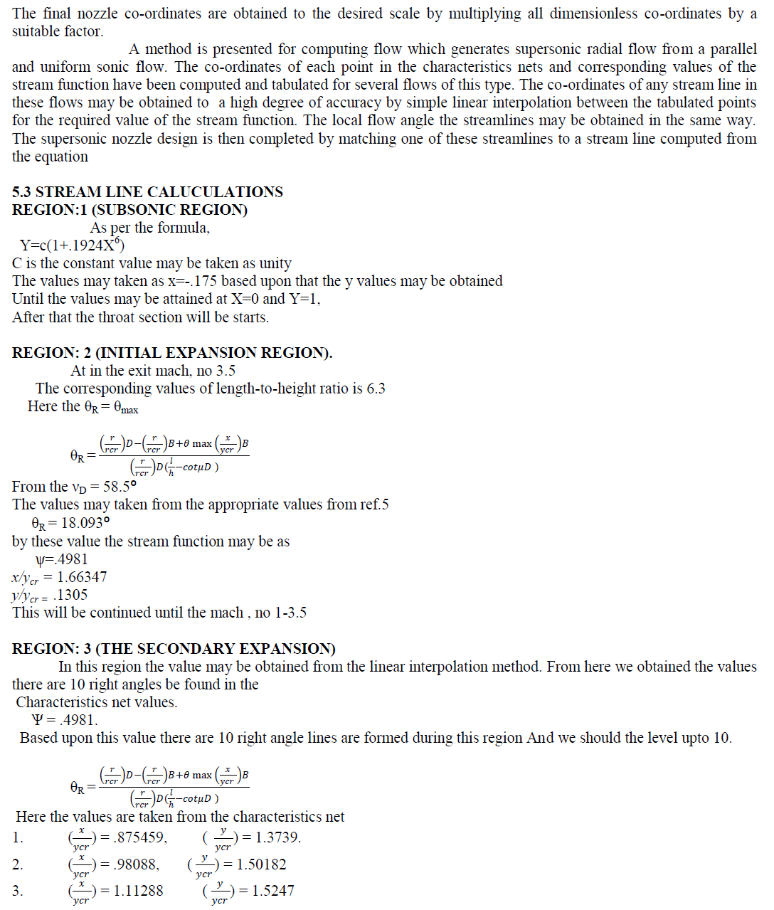
| A procedure is given for designing two-dimensional nozzles in which the streamline co-ordinates are compared directly from tabulated flow parameters and appropriate equations. The method of characteristics is used to obtain the first part of flow which consist of a continuous expansion from a uniform sonic flow to a radial flow, the Folesch equation are then used for the transition from radial flow to the final uniform flow. Information is presented which enables the design to select and compute radially the wall contour for any nozzle (or) series of nozzle for a wide range of length-to-height ratio, Mach number and wall angle at the inflection point. |
| A nozzle is determined specifying by any two of these parameters |
| 1. Length-To-height ratio. |
| 2. MACH:NO: |
| 3. Wall angle at the inflection point |
REGION OF NOZZLE |
| 4.1 1. REGION I: (sub sonic region) |
| The calculation of the subsonic portion of a nozzle is simplified by the straight sonic line. A straight sonic line normal to the axis is always obtained when the velocity gradient along the x-axis vanishes at the sonic point. |
| Y= C (1+.1924X6) |
| Where, c- constant. |
| 2. REGION II: (THE INITIAL EXPANSION) |
| The computation for region II is based on the boundary conditions of a uniform parallel flow along sonic line with Y-axis. |
| 3. REGION III: (THE SECONDARY EXPANSION) |
| The flow in region III was computed by the method characteristics by using the initial conditions which result in a continuous curvature and velocity gradient along the all stream lines between the sonic line and the Mach, line. |
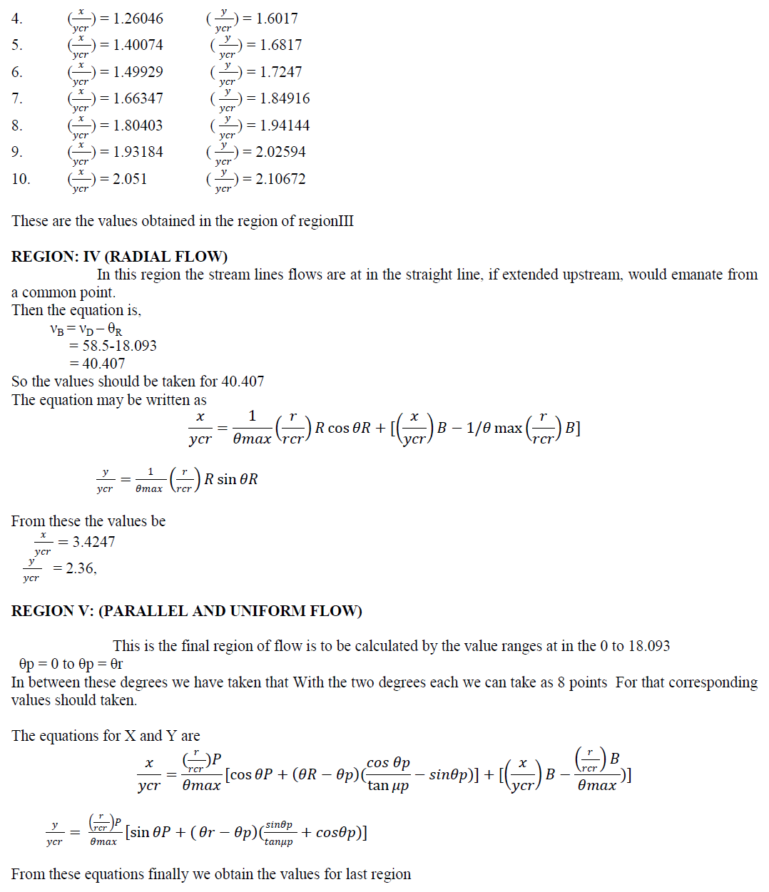
| 4. REGION IV: (THE RADIAL FLOW) |
| A plane radial flow (or source flow) is defined as out in which all dependent variables are a function only the radius from a fixed point in the plane. It is the same as the well-known area ratio equations in a one-dimensional flow. The stream lines within the radial flow are straight lines, which are extended, would get from the original of the radial flow. |
| 5. REGION V: (THE FINAL TRANSITION) |
| It is bounded by the radial flow Mach, line and the straight Mach, line. The coordinates for any stream line within this flow are by the equations. |
MODEL CALULATION |
| 5.1 DESIGN CALCULATION: |
| For design the nozzle standard conditions are to be assumed. Because of the test is made at in the sea-level condition. So there should be no vacuum. The pressure is at in ambient pressure. |
| 1. Chamber pressure, Pc=1000Psi (or) 6.894*106 Pa. at in the ground level the ignition temperature of the propellant may be taken. |
| 2. Exit pressure , Pe |
| 3. Ambient pressure, Pa=1.01325*105 Pa at in atmospheric pressure. |
| 4. The chamber temperature Tc=2500k. This temperature is taken from the propellant Liquid oxygen & Liquid hydrogen. The temperature is 45000F ( Table: I) |
| Where Pe=Pa at in the sea level condition. |
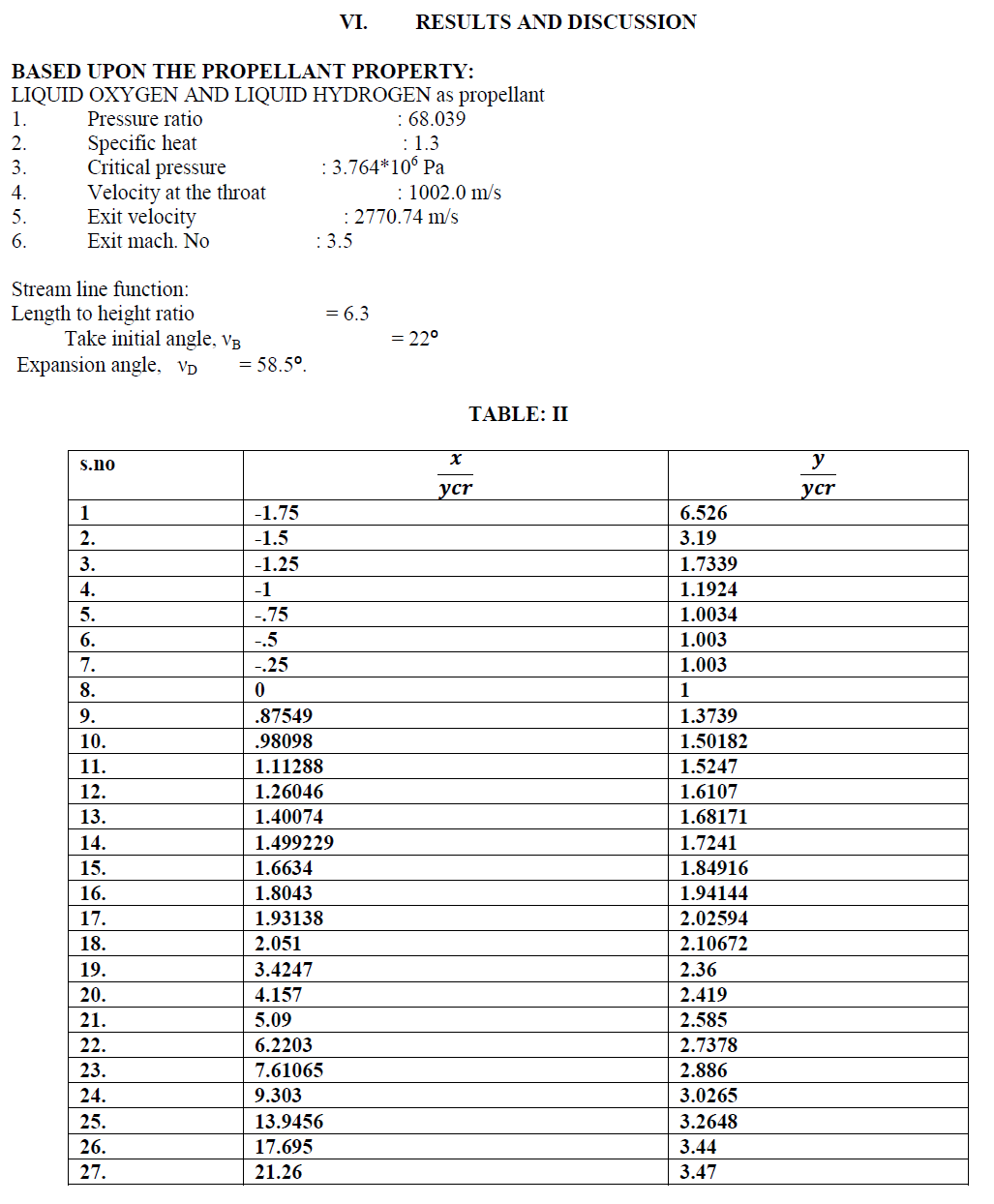
| All the parameters are to consider when the nozzle Is to be designed it is suitable to get the values for exit Mach, no. conditions. As the temperature is must for this condition because it should at in high temperature. The material should be ability withstand at high temperature at nozzle walls. |
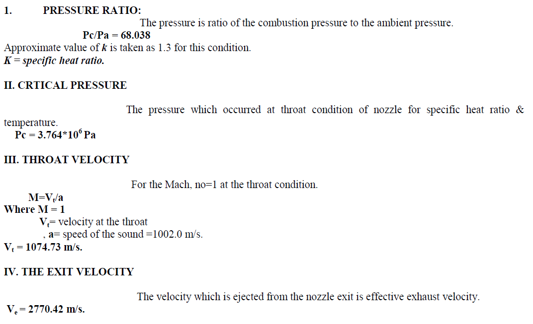
| The following values property is based upon the propellant mixture and initial values of the static thrust condition. The formulas used for the obtaining these values are derived from the rocket propulsion system. |
 |
 |
 |
 |
 |
 |
CONCULSION |
| In this project Phase-I the length and exit area of the rocket nozzle are optimized partially. For optimization, region to region method is used. The 2D model of nozzle is created by using CATIA software and it is to be converted into 3D model. Finally the optimized rocket nozzle efficiency will be compared with the existing one. |
FUTURE WORK |
| Based on the calculations we have to design the nozzle in 2D form. For further work I have to covert this into 3D model. Also analyse the 3D model using the software CFD (Computational Fluid Dynamics) and to obtain the flow behaviour acting in the model. |
References |
|