ISSN ONLINE(2319-8753)PRINT(2347-6710)
ISSN ONLINE(2319-8753)PRINT(2347-6710)
| R.Suresh, M. Rajesh Kumar, K. Tamil selvam Department Mechanical Engineering, Anna University, Knowledge institute of technology Salem, Tamilnadu, India |
| Related article at Pubmed, Scholar Google |
Visit for more related articles at International Journal of Innovative Research in Science, Engineering and Technology
Blast furnace represents the dominate hot metal making production process worldwide and a largest unit in an integrated steel plants. The purpose of the blast furnace is to chemically reduce and physically convert iron oxides into liquid iron called hot metal. Handling of blast furnace units is not a simple issue. During the blast furnace operation various hazards like fire and explosion, blast furnace gas which is more hazardous and explosive in nature are arise. Safety analysis requires a thoroughly methodological investigation such analysis must include the ability to deal with problems involving human error. In this paper what if analysis a systematic brain storming approach is applied to the two nodes of blast furnace units to find out the hazards and its consequences arise during blast furnace operation. Based on the results of what if analysis two nodes are prioritized and safety precautions, recommendations were suggested for the safe operation of blast furnace nodes.
Keywords |
| Blast furnace, what if analysis, hazard, blast furnace gas, fire and explosion |
INTRODUCTION |
| A huge increase in steel production in recent years requires a sufficiently large production of iron. A prominent technology in the production of iron is even now blast furnace technology, which delivers iron in the form of hot metal. Blast furnace iron making faces a lot of difficulties to convert iron ore into pig iron. Various operational problems like refractory bricks lining damage, furnace pressurization, increase in temperature makes the blast furnace more vulnerable and lead to fire and explosion. It is very important to seek an effective and accurate method to improve the safety systems of blast furnace units. Succeed and maintaining a safe state during abnormal situations is essential for the safety design and safe operation of blast furnace. In recent years various reliability engineering techniques are used to improve the blast furnace safety. To analyze the hazards and to improve the blast furnace safety one of the most effective and critical brain storming techniques what if analysis is used in this paper. |
| A. Blast furnace |
| Blast furnace produces pig iron from iron ore by reducing action of a carbon at a high temperature in the presence of fluxing agent such as limestone. Iron making blast furnace consists of several zones a crucible shaped hearth at the bottom of the furnace, an intermediate zone bosh between hearth and stack. In a blast furnace iron ore, coke and limestone are continuously charged at the top of blast furnace. While enriched oxygen from air separation plant is blown into the bottom section of the furnace, so that chemical reactions take place throughout the furnace as the material moves downward. The end product are usually molten metal and slag phases tapped from the bottom at regular intervals and blast furnace gas exiting from the top of furnace is cleaned in gas cleaning plant and used as a fuel at captive power plants, for the burners at sinter plants, vacuum degassing boiler, pulverized coal injection plant and in furnace of bar and rod mill. Blast furnace gas contains carbon monoxide which is highly toxic and flammable and a small amount of hydrogen and methane. |
| B. What if analysis |
| What if analysis technique is based on the principle of team approach to analyze hazard. The What if analysis team made up of individuals with varying backgrounds and expertise the expertise is brought together during analysis sessions and through a collective brainstorming effort that stimulates creativity and new ideas a thorough review of the process under considerations is made. The team focuses on specific portions of the process called nodes. Generally they are identified from the P&ID of the process before the study begins. Then a series of what if type questions are asked between the team members. Once the causes are identified the team list the consequences, safeguards and any recommendations deemed appropriate. The process is repeated for the next deviation and so on until completion of the node. The team moves on the next node and repeats the process. The analyze procedure formally examines all equipment step by step as well as deviation from the normal operation. What if analysis report includes all the deviation and their causes, consequences, implemented protection and the resulting suggestions. It can be successfully applied not only the existing plant but also to new designed techniques and equipment. A what if analysis is normally executed by a multidisciplinary team of experts in process plant design operation and maintenance who under adequate leadership systematically analyze the process P&ID to find out the causes and consequences of every abnormal deviation of the Process variables. |
| II. Node 1 |
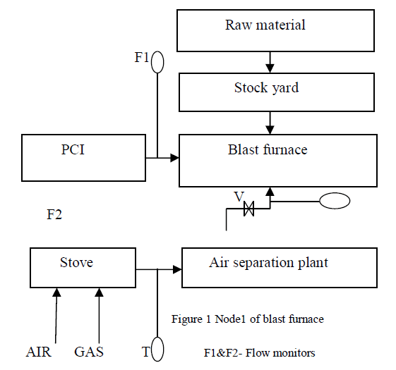
| Node 1 (figure 2.1) consists of raw material yard, blast furnace, pulverized coal injection, stove, air separation plant. |
| The raw material namely iron ore, coke, limestone dolomite and quartzite will come from different sources. They will be stacked in the raw material storage yard transported by conveyor system to the stock house. In blast furnace raw materials along with fluxes are reduced with metallurgical coke at a temperature of around 1400 degree Celsius to produce hot metal. Pulverized coal injection is a method for improving the performance of a blast furnace. Air separation plant installed to produce oxygen and nitrogen. Oxygen for enrich the blast inside the furnace and nitrogen for purging purpose. |
 |
| Node 2 |
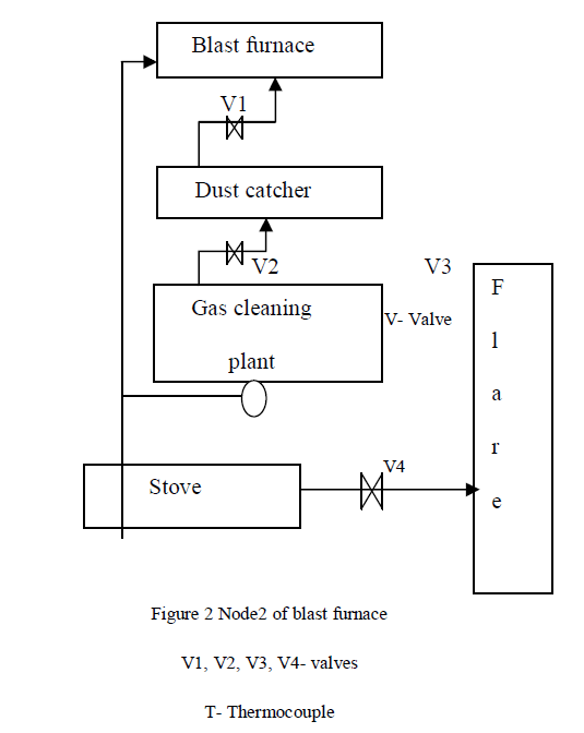
| Node 2. It consists of gas cleaning plant, dust catcher, stove, flare tower. Node 2 units help for the plant for various purposes and to control the emission levels to a predetermined level. Flue gas from the top of the blast furnace is collected in a dust catcher and then transport to the gas cleaning plant through pipe lines. In gas cleaning plant gas is cleaned by water spray. Protection. Dust catcher removes the heavy dust particles coming along with the blast furnace gas by reducing the velocity of the gas so that dust particles are left as the gas lost its ability to carry the dust particles. Flare system used to burn the dust and gases that cannot be cleaned by a gas cleaning plant. Flare consists of main components like structure pipe, flare burner and ancillary equipment for burning the flue gas LPG is used as fuel in flare system. It also provides safety during the emergency situation. Safety valves connected in the nodes help to reduce the pressure of gas flow and prevent the pipelines from damage |
 |
 |
 |
 |
 |
| communication, in place such that adequate risk control is maintained. |
CONCLUSION |
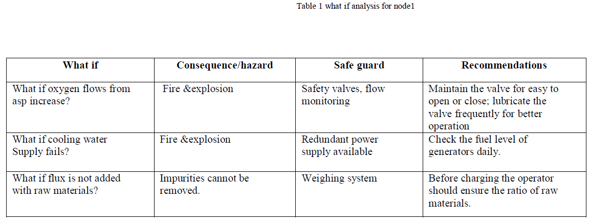
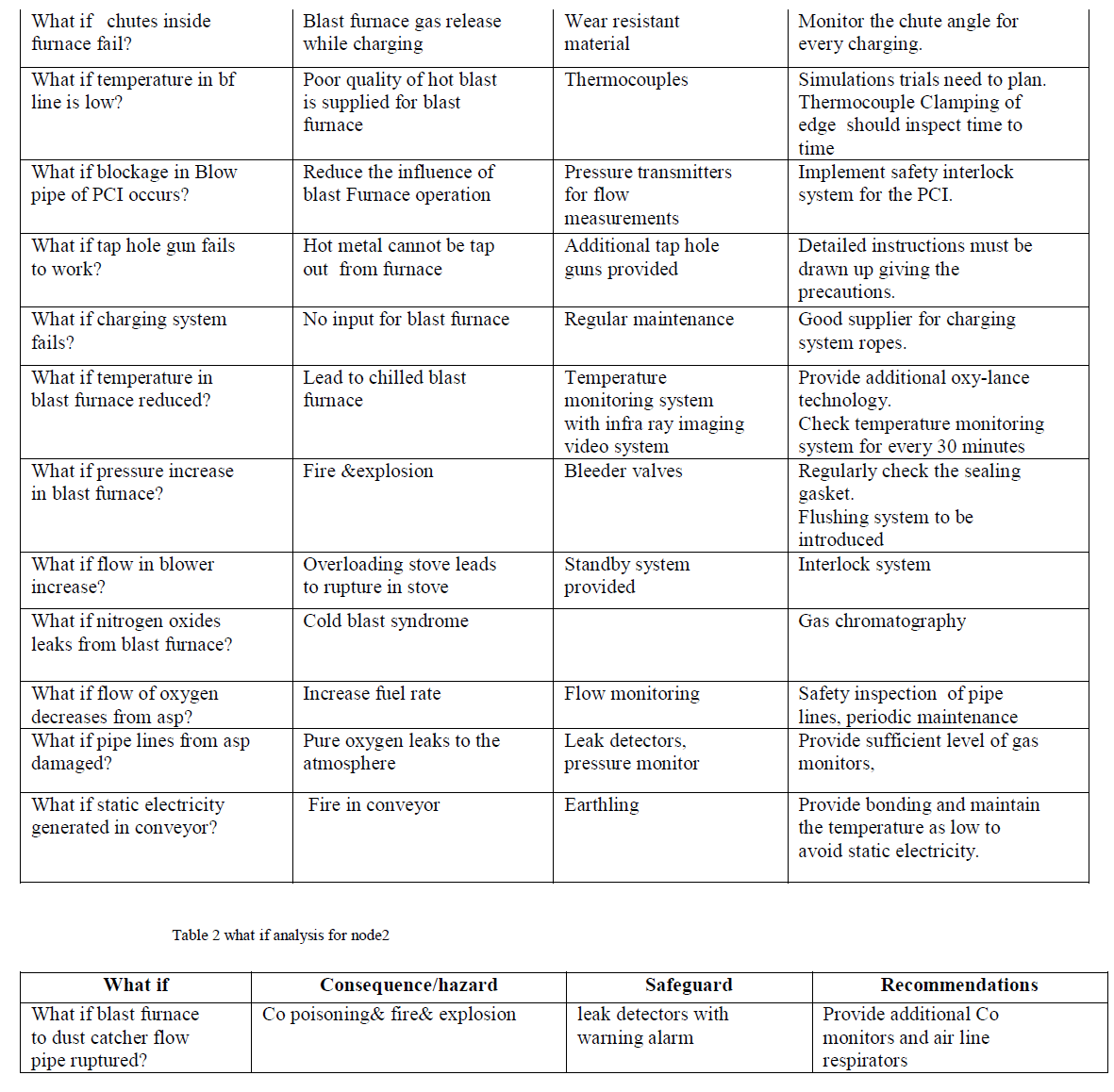
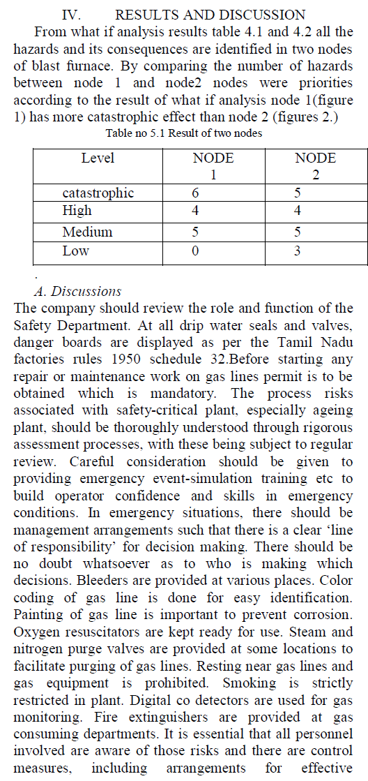
| What if analysis is a critical brain storming technique which is widely used in many areas and industries. What if analysis was conducted between the two nodes of blast furnace successfully. From the result table 1 and 2 of analysis nodes were compared and priorities. Node 1 figure no 2.1 has high risk values and more no of catastrophic and high hazards than the node 2 figure no 2.2 Based on these values safety precautions and recommendations were suggested for the blast furnace operational units. |
References |
|