ISSN ONLINE(2319-8753)PRINT(2347-6710)
ISSN ONLINE(2319-8753)PRINT(2347-6710)
| K. Vishnu Priya and I. Kathir Electrical and Electronics Engineering, Anna University, Mepco Schlenk Engineering College, Sivakasi-India |
| Related article at Pubmed, Scholar Google |
Visit for more related articles at International Journal of Innovative Research in Science, Engineering and Technology
This paper propose a maximum power point tracker (MPPT) for subwatt photovoltaic (PV) module. This provides maximum output power by tracking continuously the maximum power point (MPP), which depends on the temperature and an irradiance condition and is used in wireless sensor network (WSN). Dynamic power management technique is used to reduce the power consumption of the PV module and the system is dynamically reconfigured to activate the minimum number of modules. An ultra low power microcontroller is used to implement MPPT algorithm for low processing time and low circuit complexity. A perturb and observe maximum power point tracking (P&O MPPT) is used for low cost implementation. The pulse frequency modulation (PFM) technique is used for low power level which adjusts the switching activity of available power and this leads to reduce its efficiency at higher ripple current. This can be solved by implementation of current limiter for high switching frequency. The simulation studies have been carried out by NI MultisimTM 12.0.
Keywords |
| Maximum power point tracking (MPPT), solar photovoltaic (PV) cells, dynamic power management (DPM), wireless sensor network (WSN). |
INTRODUCTION |
| The primary and secondary batteries are used for low power device. Primary batteries are non rechargeable and it is cheaper. Secondary batteries are rechargeable which is used in mobile phones. |
| The extracted voltage and current of PV module is used to calculate the power. This is applicable to low power PV module less than 1 W. The voltage at which the maximum power occurs in PV module gives Maximum Power Point (MPP), the MPPT includes in a charge controller used for extracting maximum available power from PV module. Perturb and Observe (P & O) tracking algorithm is used for its flexibility and simple construction. The major drawback of P&O algorithm is not determines the actual reach of MPP under steady state operation as the output power oscillates around the MPP. |
| High performance MPPT includes pulse width modulation (PWM), used in large scale PV module, whereas, low performance MPPT includes PFM used in small scale PV module. PFM is used instead of PWM to attain better efficiency at low power levels. PWM continuously activates the switches of the converter at a fixed frequency whereas PFM adjusts the switching activity of the available power. The efficiency gets reduced for higher ripple current. To avoid this problem current limiter is used for higher switching frequency. |
| The power obtained from PV module as light energy is converted into electrical energy A diode is connected between the solar PV module and DC-DC converter in order to avoid the discharge of batteries to PV module at null or low irradiance. The power consumption at reduce level of MPPT to be achieved for the subwatt of PV module power [7]. |
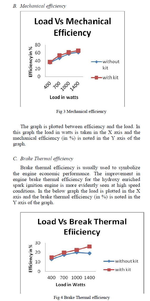 |
| A block diagram of the proposed system is shown in Fig. 1. It consists of PV Module, DC-DC boost converter, MPPT and battery. The calculated power of voltage and current of PV module is supplied to MPPT controller; P & O MPPT algorithm is used. The pulse frequency modulating signal is applied to DC-DC boost converter to trigger the MOSFET switch. The output voltage of DCDC converter is stored in battery which can be used for various applications such as LED, LCD display and DC motor drives. |
| A. Photovoltaic (PV) Cell |
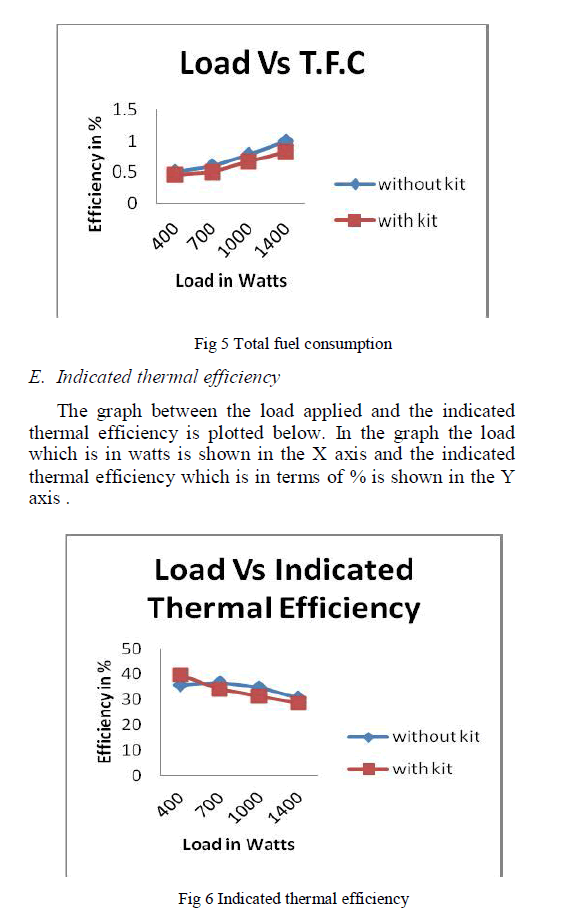
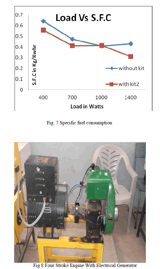
| A PV cell is a voltage limited current source at a wide range of operation where battery acts as a voltage source. There is an optimal operating point, with specific current and voltage values, at which the power extracted from the cell is maximize. The tracking of maximum power is MPP (Maximum Power Point) [2]. The equivalent circuit of PV cell is shown in Fig. 2. The solar PV cell generates current is represented as IPV , the generated current varies for different temperature and irradiance condition. The series resistance (Rs) of the solar cell is not a perfect conductor. The shunt resistance (RP) causes leakage current from one terminal to other due to poor insulation. The resistance values of ideal solar cell is Rs =0 and RP=∞.).The output current of PV cell calculated using (1) and power calculation of PV cell using (2). |
 |
 |
| The MPPT controller is the voltage at which the maximum available power from PV module gets extracted effectively by tracking. MPPT checks the output of PV module, which compares the battery voltage then fix the maximum power of PV module which is used to charge the battery. It can also supply the power to DC load, which is connected directly to the battery. The flowchart of Perturb and Observe Maximum Power Point Tracker (P & O MPPT) algorithm is shown in Fig. 3. The criteria of P & O algorithm is the operating voltage of PV module is perturbed in a given direction and if the power from PV module is increases then the operating point has moved toward the MPP else the operating point has moved away from the MPP then the power drawn from the PV module. The operating voltage perturbed in same direction and observes in reversed same direction [1]. |
| C. DC–DC Boost Converter |
| The unregulated DC voltage obtained from PV module gets fluctuated due to changes in irradiance and temperature is converted into regulated DC voltage, to increase the output voltage boost DC-DC converter is used. The output DC voltage is stored in battery. |
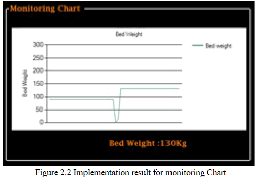
| The basic principle of a DC-DC boost converter is shown in Fig. 4. It consists of two distinct states, on state and off state. In on states, the switch S is closed, results in increasing of inductor current iL flows through the fly back diode D, the capacitor C and the load R. This result in transfer of energy accumulated during on state into the capacitor C. In off states, the switch S is open, the current reduced as the impedance is high [4]. The maintenance of current flow towards the load is eradicated by magnetic field produced during on state. Thus the polarity is reversed. As a result, two sources will be in series causing a higher voltage to charge the capacitor through the diode D. |
 |
| D. Battery |
| The output voltage of DC-DC boost converter is stored in the battery. AA NiMH batteries connected in series used store more output voltage. |
TECHNIQUES |
| A. Dynamic Power Management (DPM) Technique |
| To reduce power consumption, the proposed system is dynamically reconfigured to activate the minimum number of modules. DPM technique is used to smooth variations of the operating conditions of the PV module .Under slow variation of irradiance and temperature T and ΔT will be similar in contiguous cycles. Consequently, it is possible to predict when any module is needed and activate it a short time before. |
| B. Pulse Frequency Modulation (PFM) Technique |
| PFM is one type of modulation use analog signal at two levels (1 and 0). In other words, the frequency of the pulse train is varied in accordance with the instantaneous amplitude of the modulating signal at sampling intervals. The advantage of pulse frequency modulation is to provide better immunity to noise interference than Pulse Amplitude Modulation (PAM). |
| The feedback signal is connected to a hysteresis comparator with a limits between (high voltage) VH and (low voltage) VL and the switching frequency can change by adjusting the values of VH and VL. Both are determined by the hysteresis comparator. The modulated PFM signal will control the on and off duration of power MOSFET to stabilize the output voltage [8]. |
| Pulse Frequency Modulation technique (PFM) is a derivative of Switch-Mode Operation to improve the power conversion efficiency of a switching regulator at light load currents [4]. This feature is especially useful for systems operating in a “standby” mode, where that power consumption of an order magnitude lower than the fully active mode. When the output current drops below a predetermined threshold the regulator begins to skip pulse which reduces switching losses. At light output currents these switching losses tend to dominate the overall losses for the regulator circuit. |
C. Wireless Sensor Network (WSN) |
| The voltage and current signal are supplied to Analog and Digital (ADC) converter, the converted signal is the input of microcontroller. RF transceiver is used as wireless signal. The operation of the wireless sensor node is to sense external analog signals such as voltage and current of the PV module, and to communicate the sensed information to the gateway node in short time. Received data send to DC-DC boost converter [9]. |
 |
CIRCUIT IMPLEMENTATION |
| The simulation of maximum power point tracker for subwatt PV module using NI MultisimTM 12.0 is shown in Fig. 6. The simulation circuit consists of PV module, P & O MPPT algorithm and DC-DC boost converter.Voltage control voltage source is used between PV module and DC-DC boost converter. |
 |
 |
| The Maximum power of PV module versus power consumption of MPPT controller is shown in Table I. The consumed power in MPPT is lower, for lower power PV module is shown in Fig. 11 and this curve shows the increase in power consumption for increase in output PV module power. The PV module power in nano watts (nW) and power consumption of MPPT in pico watts (pW) is achieved. |
 |
CONCLUSION |
| The output power of PV module is delivered to both P & O MPPT controller and boost DC-DC converter. The lower power consumption of P & O MPPT for sub watt photovoltaic (PV) module is achieved. The PFM generating signal for 80 KHz frequency from MPPT is applied to boost DC-DC converter. The generating pulse frequency is applied to IRFD110 MOSFET switch. The output voltage of DC-DC boost converter is stored in battery which can be useful for various real time applications. |
References |
|