ISSN ONLINE(2319-8753)PRINT(2347-6710)
ISSN ONLINE(2319-8753)PRINT(2347-6710)
| SaadOboudi Associate Professor, Department of Physics, College of Science, University of Baghdad, Baghdad, Iraq |
| Corresponding Author: SHARMA VIVEK, E-mail: vivek03sharma@rediffmail.com |
| Related article at Pubmed, Scholar Google |
Visit for more related articles at International Journal of Innovative Research in Science, Engineering and Technology
Uniform and adherent cobalt oxideCo2O3 andcopper doped cobalt oxide Co2O3:Cu films have been deposited by using spray pyrolysis technique (SPT) on glass substrates. For investigating the structure and optical properties of thin films, X-ray diffraction (XRD) and UV-vis spectra were used. Increasing dopant caused an increase in the crystal size. The optical properties and dispersion parameters of cobalt oxide have been studied as a function of Cu dopant concentration. Changes in direct optical band gap of cobalt oxide films were confirmed after doping,the optical energy gap Eg increased from 1.48 and 1.95 eV for the undoped Co2O3 to 1.55 and 2.05 eV with increasing the doping concentration of Cu to 5%. The changes in dispersion parameters and Urbach tails were investigated. An increase in the doping concentration causes a decrease in the average oscillator strength from 45.60 to 25.32. The single-oscillator parameter has been reported.
Keywords |
| TCOs, Dispersion parameters, Spray pyrolysis, Cobalt Oxide. |
INTRODUCTION |
| The optical properties of thin films are very important for many applications, including interference devices, such as antireflection coatings, laser mirrors and monochromatic filters, as well as optoelectronics, integrated optics, solar power engineering, microelectronics and optical sensor technology depending on the reflectance and transmittance properties of the films during their preparation. Transparent conducting oxides (TCOs) are well known and have been widely used in optoelectronics and transparent electronics as well as in different research fields. Most of the existing TCOs are n-type, whereas it is very difficult to prepare binary metal oxides with p-type conductivity[1].Among the transition metals, copper and cobalt are the most active for the decomposition of nitrous oxide and removal [2,3]. Cobalt oxide is an important functional material for a wide range of technological applications such as heterogeneous catalysts, anode materials in Li-ion rechargeable batteries, magnetism, and optical devices [4,7], gas and humidity sensors[8,9],solar selective absorber, pigment for glasses and ceramics [10], catalyst for oxygen evolution and oxygen reduction reaction [11,12]. It is widely used as an electrochromic material [13],electrochemical capacitors for high power devices in energy storage systems (supercapacitors) [14,15]. Owing to the influence of doping on the properties of materials, the controlled preparation of cobalt oxide of different doping materials and concentrations are always the researcher’s purpose.This paper reports the influence of Cu dopant on the preparation and properties of cobalt oxide (Co2O3) thin films by spray pyrolysis technique (SPT). The accurate determination of the optical properties of these materials is important, not only in order to know the basic mechanisms underlying these phenomena, but also to exploit and develop their interesting technological applications. |
II. EXPERIMENTAL DETALIS |
| Cobalt (II) chloride hydrateCoCl2.6H2O 0.1M as matrix material and copper chloride (CuCl2.2H2O) 0.1Mas a doping agent with different Cu/Co mole ratio = 1%, 3% and 5% have been dissolvedin de-ionized water and ethanol to form the final spray solution, these two starting solutions were used for deposition of Co2O3:Cu thin films on glass substrate. A few drops of HCl were added to make the solution clear,a total volume of 50 ml was used in each deposition. The spray pyrolysis was done by using a laboratory designed glass atomizer, which has an output nozzle of1 mm. The films were deposited on preheated glass substrates at a temperature of 450°C. With the optimized conditions that concern the following parameters, spray time was 10 sec. The period between spraying processes was about 3 min, this period is enough to avoid excessive cooling of glass substrate. The carrier gas (filtered compressed air) was maintained at a pressure of 105 Nm-2, distance between nozzle and substrate was about 29 cm, solution flow rate 5 ml/min. Thickness of the sample was measured using the weighting method and was found to be around 300nm. A thermocouple was fixed to the substrate surface and the temperature was measured at the four corners of the glass substrate surface, Optical transmittance and absorbance were recorded in the wavelength range (300-900nm) using UV-visible spectrophotometer (Shimadzu Company Japan). Optical transmittance and absorbance were reported in order to find the effect of doping on the parameters under investigation. |
III. RESULTS AND DISCUSSION |
| Structural analysis of cobalt oxide films was carried out on a Philips x-ray diffractometer system with CuKïÃÂá target by varying diffraction angle 2θ from (20-80) degree. XRD pattern of films reveal formation of Co2O3 cubic phase with (1 1 1) and (2 2 2) planes in all samples and CuCoO2 in samples that contain Cu. Because of doping, major XRD peaks became sharper and improvement in the crystallinity can be observed. Also, by increasingdopant, another phase of hydrous Cobalt oxide Co3O4 wasemerged. The average grain size of the Co2O3 thin films was calculated using the Debye–Scherrer’s equation [16-18]: |
| Where D is the grain size, λ is the x-ray wavelength, θ is the Bragg angle and ïÿýïÿý is the full width at half-maximum of diffraction peak. Table (1) shows average grain size which are varied between 21-38 nm for different samples. They were increased by increasing dopant. It is noteworthy that we could achieve the oriented growth of Co2O3 onto amorphous glass substrate using the spray pyrolysis technique. The oriented growth might be due to the heating of substrates during deposition. |
 |
| Table (1): Results of X-ray pattern for Co2O3-Cu thin films |
| The optical properties of films by means of optical absorption in the UV to Vis region of (500–900) nm have been investigated. The absorption coefficient (α) could be calculatedby using the following relation [19]: |
 ........................(2) ........................(2) |
| Where (A) is the absorption and (t) is the film thickness. Fig. (1) Shows the dependence of the absorption coefficient (α) on the wavelength.The absorption coefficient decreases with increasing the doping concentration of Cu. It can be seen from the figure that the absorption coefficient decreases up to wavelength 620 nm and then increases upto 750 nm and again decreases from 780 nm, depicting two regions of optical transitions. Similar type of results was reported by Shinde et al. [20]. Also it can be observed from the figure that the absorption coefficient decreased with increasing the doping concentration of Cu to 5%. |
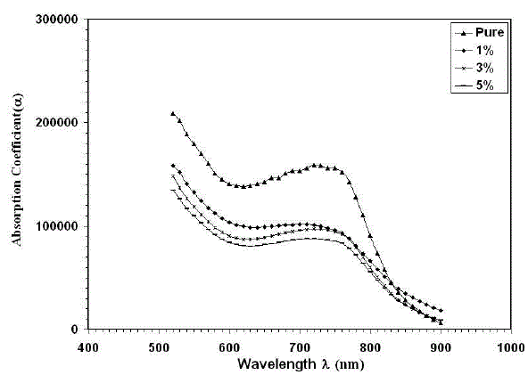 |
| Fig. 1Variation of Absorption coefficient with wavelength for thin films |
| From the transmittance data and according to Tauc [21] relation, (αhυ)2versus incident photon energy (hυ), plots were obtained. The graphs are represented in Figure 2. As cobalt oxide is a direct transition semiconductor, the estimated band gap energy values are found to be 1.48 and 1.95 eV for the un-dopedfilms, which is in consistent with the band gap energy of cobalt oxide films reported earlier for spray pyrolysis method [22,23]. After doping and increasing the doping concentration to 5% of Cu, the band gap energy values were increased to 1.55 and 2.05 eV. Many reports exist for cobalt oxides, such as CoO andCo3O4 but the literature is deficient of the information on Co2O3thin films, particularly on its energybandgap. Drasovean et al. [24] reported 2.09-2.10 eV and 1.25-1.30 eV for direct and indirect bandgaps respectively for Co3O4 thin films. However, bandgap values of 2.2-2.8 and 1.4-1.8 eV have also been reported for CoO and Co3O4, respectively [25]. Thevalues obtained in this work are close to others previously reported for the direct transition in CoO, Co2O3, and Co3O4 thin films [24-27]. It can be seen from fig. (2)that all films have two different regions was put in evidence, corresponding to different phases. It was proved that Eg values, corresponding to these phases. The activation energy calculated from the slopes of graphs represents the location of trap levels below the conduction band. |
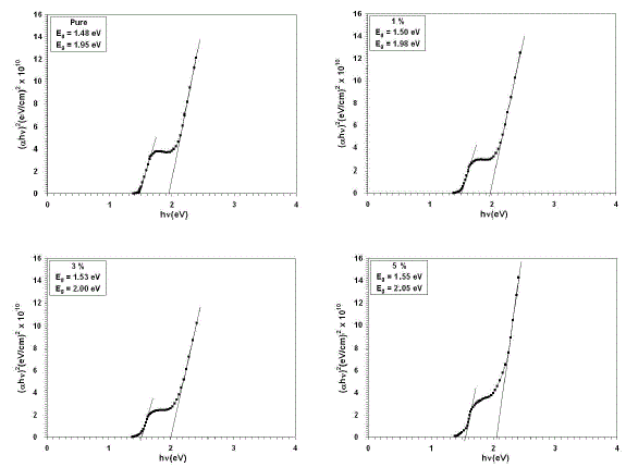 |
| Fig. 2(αhυ)2 for thin films versus photon energy |
| The incorporation of impurity into the semiconductor often reveals the formation of band tailing in the band gap. The tail of the absorption edge is exponential, indicating the presence of localized states in the energy band gap. The amount of tailing can be predicted to a first approximation by plotting the absorption edge data in terms of an equation originally given by Urbach [28]. The absorption edge gives a measure of the energy band gap and the exponential dependence of the absorption coefficient, in the exponential edge region Urbach rule is expressed as[21,29]: |
| α = α° exp (hυ / EU) ………………… (3) |
| Where α° is a constant, EU is the Urbach energy, which characterizes the slope of the exponential edge. Fig. (3)showsUrbach plots of the films. The value of EU was obtained from the inverse of the slope of lnα vs. hυ and is given in Table (2). The dopants change the width of the localized states in the optical band. EU values change inversely with the optical band gap. The Urbach energy values of Co2O3, Co2O3:Cu 1%, Co2O3:Cu 3%, and Co2O3:Cu 5% films were calculated to be 152, 110, 102 and 81meV respectively. The decrease of EU suggests that the atomic structural disorder of Co2O3 films increase by copper doping. This behavior can result from increasing the concentration of point defects induced by the dissolution of Cuatoms in Co2O3 crystals and formation of solid solution. So, this decrease leads to a redistribution of states, from band to tail. As a result, both an increase in the optical gap and a narrowing of the Urbach tail are taken place. |
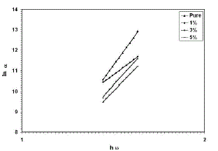 |
| Fig. 3 lnα versus photon energy for thin films |
| The refractive index dispersion plays an important role in optical communication and designing of the optical devices. Therefore, it is important to determine dispersion parameters of the films. The dispersion parameters of the films were evaluated according to the single-effective-oscillator model using the following relation [30,31]: |
| n2 -1 = [EdEo/ Eo 2− E 2] ………. (4) |
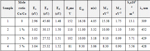
| The physical meaning of the single-oscillator energy Eois that it simulates all the electronic excitation involved and Ed is the dispersion energy related to the average strength of the optical transitions [32], which is a measure of the intensity of the inter band optical. This model describes the dielectric response for transitions below the optical gap. (n2−1)−1 vs. (hυ)2 plots for the films was plotted as shown in Fig. (4). Eo and Ed values were determined from the slope, (EoEd)−1 and intercept (Eo/Ed), on the vertical axis and are given in Table (2). Eo values increased with the dopants as the optical band gap increase. According to the single-oscillator model, the single oscillator parameters Eoand Edare related to the imaginary part of the complex dielectric constant, the moments of the imaginary part of the optical spectrum M−1 and M−3 momentscan be derived from the following relations [33]: |
| Eo 2 = M−1 / M−3 ……….. (5) |
| Ed 2 =M3 −1 / M−3 ………. (6) |
| The values obtained for the dispersion parameters Eo, Ed, M−1 and M−3 are listed in Table (2).The obtained M−1 and M−3 moments changes with the dopants. For the definition of the dependence of the refractive index n on the light wavelength (λ), the single-term Sellmeier relation can be used [30]: |
| n2 (λ) − 1 = So.λo 2/ 1 − (λo/λ)2 ………. (7) |
| Where λois the average oscillator position and Sois the average oscillator strength. The parameters So and λoin Eq. (7) can be obtained experimentally by plotting (n2 – 1)−1 against λ−2 as shown in Fig. (5), the slope of the resulting straight line gives 1/ So, and the infinite-wavelength intercept gives 1/ So λo 2. The results shows an increase in the band gap which may be attributed to the presence of unstructured defects, that decrease the density of localized states and cause a narrowing in the Urbach tail and consequently increase the energy gap. |
 |
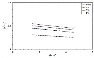 |
| Fig. 4 Variation in (n2 – 1)−1 as a function of (hυ)2 for thin films |
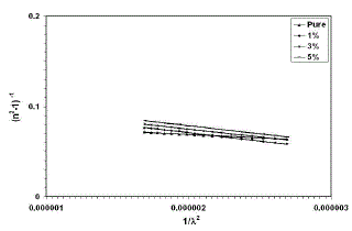 |
| Fig. 5 Variation in (n2 – 1)−1 as a function of (λ)-2for thin films |
| The optical conductivity was calculated using the relation [34]: |
| σ = α n c / 4π …………….(8) |
| Where c is the velocity of light.Fig.(6) shows the variation of optical conductivity with the wavelength. It can be seen that the optical conductivity decreases as the percentage of Cu in the Co2O3films increases to 5%. Also, It can be notice that the optical conductivity for all films increased in the high photon energies region and decreased in the low photon energy region, thisdecrease is due to the low absorbance of the films in that region. |
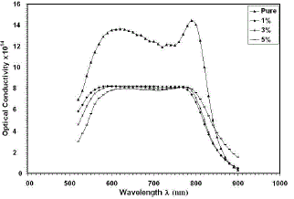 |
| Fig. 6 Optical conductivity versus wavelengthfor thin films |
| The skin depth could be calculated using the following relation [35]: |
| χ = λ / 2πk ………….….(9) |
| Where λ is the wavelength of the incident photon, k is the extinction coefficient. Fig. (7) shows the variation of skin depth as a function of wavelength for all films. It is clear from the figure that the skin depth increase as the wavelength increase, this behavior could be seen for all samples, but the skin depth increases as the doping concentration increases, so the skin depth is a transmittance related. |
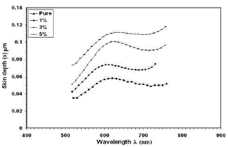 |
| Fig. 7 Skin depth versus wavelength for thin films |
IV. CONCLUSION |
| The oriented cobalt oxide thin films were prepared onto glass substrate by spray pyrolysis technique. Both doped and undoped samples were characterized. XRD pattern of films reveal formation of cubic phase with (1 1 1) and (2 2 2) planes in all samples and CuCoO2 in samples that contain Cu.Optical band gap increased due to doping.Similarly optical transmittancewas affected for moderate doping.The small value of the absorbance in the visible region offered the most promise for realizing visible laser diodes (LD) and efficient light–emitting–diode (LED) displays, by using Co2O3:Cuthin films in these devices. The single–oscillator parameters were determined. It was shown that the dispersion parameters of the films obeyed the single oscillator model, the change in dispersion was investigated and its value increased from 2.96 for Co2O3 filmsto 3.04 for Co2O3:Cufilms with increasing the doping concentration to 5%. |
References |
|