ISSN ONLINE(2319-8753)PRINT(2347-6710)
ISSN ONLINE(2319-8753)PRINT(2347-6710)
| Dr. Alaa C. Galeb, Tariq E. Ibrahim Department of Civil Engineering, University of Basrah, Iraq |
| Related article at Pubmed, Scholar Google |
Visit for more related articles at International Journal of Innovative Research in Science, Engineering and Technology
This paper aims to find the optimum dimensions of post-tension concrete (two-way ribbed) waffle slabs using standard dome size. Equivalent frame design method is used for the structural analysis and design of slab. The total cost represents the cost of concrete, strand tendons, steel, duct, grout, anchorages device and formwork for the slab. The effect of the total depth of the slab, ribs width, the spacing between ribs, the top slab thickness, the area of strand tendons and the area of steel. On the total cost of slab are discussed. The result showed that: the span to depth ratio 1/23 to 1/25 give an economic slab cost, and using 750*750 dome with 150mm rib giving minimum cost and weight. It is concluded that, the increasingin balance load, slab thickness, steel weight and total weight decrease, tendon weight increase and the 95% balance load give minimum cost.
Keywords |
| optimum dimension, prestressed waffle slabs |
I. INTRODUCTION |
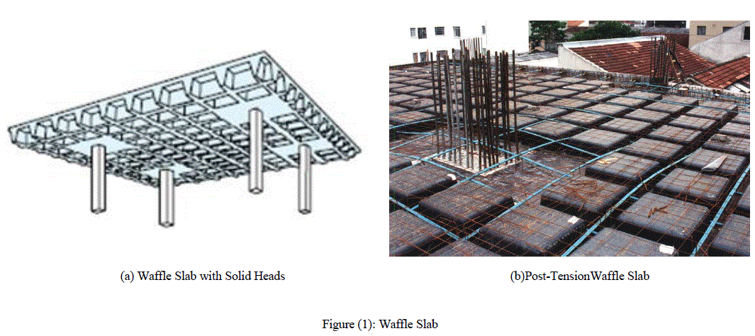
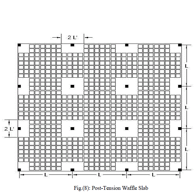
| Waffle slab construction consists of rows of concrete joists at right angles to each other with solid heads at the column needed for shear requirements Fig (1). Waffle slab construction allows a considerable reduction in dead load as compared to conventional flat slab construction since the slab thickness can be minimized due to the short span between the joists. For design purpose, waffle slabs are considered as flat slabs with solid head acting asdrop panels[1].Post-tensioning is a technique of pre-loading the concrete in a manner which eliminates, or reduces the tension stresses that are induced by the dead and live loads. Where concrete is relatively expensive, spans are generous, and it is not critical to select the smallest floor thickness, a post-tensioned waffle slab construction is likely to be the economical alternative. |
 |
| Cost optimum design of reinforced concrete structures is receiving more and moreattention from the researchers.Ibrahim[2] used mathematical programming techniques to minimize the cost of reinforced concrete T-beam floor. The floor system consisted of one-way continuous slab and simply supported T-beam. A formulation based on an elastic analysis and the ultimate strength method of design with the consideration of serviceability constraints as per ACI 318-89 code is presented. Hadi[3] presented the application of (GA) for the design of continuous reinforced concrete T and L beams based on the requirements of the Australian design standards for concrete structures, AS3600.Yokota et al.[4] formulated an optimal T cross section design (OTCD) problem with singly reinforced concrete beams for a constrained ultimate strength in the concrete/steel and solved it directly by keeping the constraints based on an improved genetic algorithm (GA). They discussed the efficiency of the proposed method and the traditional method.Sahabet al.[5] presented cost optimization of reinforced concrete flat slab buildings according to the British Code of Practice (BS8110). The objective function was the total cost of the building including the cost of floors, columns and foundations.Prasad et al.[6] elaborated the results obtained from the analytical study carried out on waffle slab medium size floor system with a view to achieve the optimum dimensions of rib spacing, its depth and width. The waffle slab has been considered as monolithically connected to band beams. Feasibility of structural design of members has been ensured under the provision of IS: 456-2000.Galeb and Atyia [7] discussed the problem of optimum design of reinforced concrete waffle slabs. Two case studies are discussedÃÂþThe first is awaffle slab with solid heads, and the second is a waffle slab with band beams along columncenterlines. Direct design method is used for the structural analysis and design of slabs. Thecost function represented the cost of concrete, steel, and formwork for the slab. The designvariables are taken as the effective depth of the slab, ribs width, the spacing between ribs, thetop slab thickness, the area of flexural reinforcement at the moment critical sections, the bandbeams width, and the area of steel reinforcement of the beams. The constraints included theconstraints on dimensions of the rib, and the constraints on the top slab thickness, theconstraints on the areas of steel reinforcement to satisfy the flexural and the minimum arearequirements, the constraints on the slab thickness to satisfy flexural behavior, accommodatereinforcement and provide adequate concrete cover, and the constraints on the longitudinalreinforcement of band beams. The results showed that For waffle slab with solid heads, the ratio of effective depth to span length (d /l )should be (1/28 to 1/19) to get the optimum design, while for waffle slab with bandbeams along columns centerlines, it should be (1/33 to 1/18). In the present paper,the optimum dimensions of post-tension concrete (two-way ribbed) waffle slabs using standard dome size is sought. The total cost represents the cost of concrete, strand tendons, steel, duct, grout, anchorages device and formwork for the slab. |
II. EQUIVALENT FRAME METHOD |
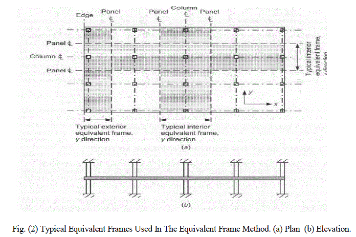
| Dean Peabody, Jr. first proposed the equivalent frame method in 1948, which has been incorporated in the ACI Code since 1956. Currently, Section 13.7 of ACI 318-11 describes the equivalent frame method and Section 18.12.1 requires prestressed slab systems use the provisions of Section 13.7 or a more detailed design procedure todetermine factored moments and shears for the design. The equivalent frame method shares many similarities in analysis with the direct-design method, but its more general approach allows it to be used to analyze moments in any practical building frame. Fig (2) shows typical equivalent frames used in the equivalent frame method. |
 |
III. BASIC CONCEPT |
| In the equivalent frame method, the slab of a building is divided into middle strips and column strips for analysis[8]. Figure (3) below illustrates how the middle and column strips are defined in a slab. |
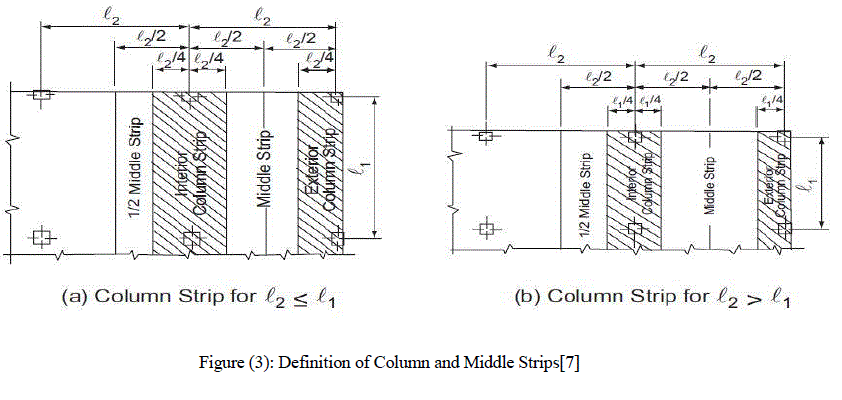 |
| ACI 318M-11 defines the width of a column strip as 0.25l1 or 0.25l2, whichever is less. The middle strip width is determined by the two column strips that bound it. The moments in the column strip frames are calculated using the moment distribution method. The equivalent frame method assumes the moments to be uniformacross the strips. The stiffness of the slab and columns must be found, as well as the carryover factors, in order to determine the moments across the section of frame using moment distribution. |
IV. MOMENT DISTRIBUTION |
| The moment distribution method uses relative stiffness (K), carryover factors (COF), distribution factors (DF), and fixed end moments (FEM), to determine the distribution of moments in a structure. The stiffness, carryover factors, distribution factors, and fixed end moments are found using the Column Analogy Method.[9]The stiffness of the columns for the equivalent frame method must be adjusted for torsion due to the attached slab or beams[7]. The equivalent column stiffness becomes |
 |
| where |
| Kec:is the equivalent column stiffness, |
| Kc:is the sum of the flexural stiffness's of the columns, and |
| Kt:is the torsional stiffness of the attached torsional members calculated by |
 |
| where |
| Ecs: is the modulus of elasticity of the slab concrete, |
| l2:is the length of the transverse spans on each side of the column, |
| c2:is the width of the column, and |
| C:is a constant, roughly equivalent to a polar moment of inertia, calculated |
| By subdividing the cross section into rectangles and carrying out the following summation |
 |
| where x is the shorter side of the rectangle and y is the longer side. |
| ACI 318 Section 13.7.5 requires the added stiffness of torsional members be considered in design this. Drop panels are included in the calculation of the torsional stiffness when used in a slab. |
V. Load Balancing |
| T.Y. Lin’s technique of load balancing is the most widely used method for design of prestressed concrete slabs[10]. Fig. (4) below illustrates the general approach to load balancing. |
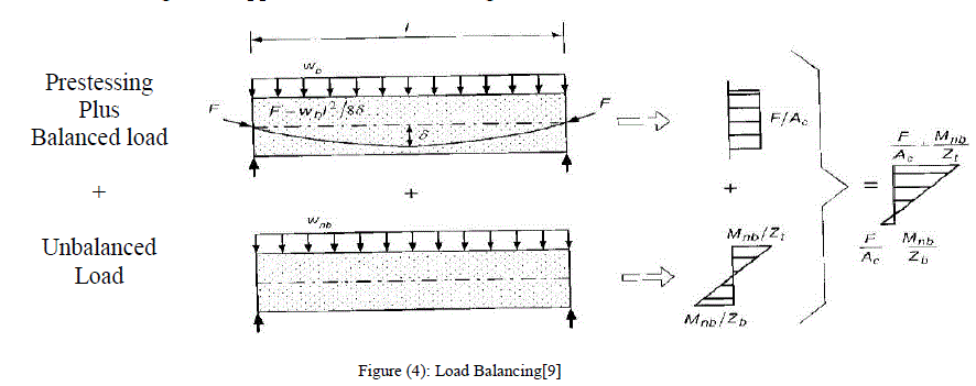 |
| The load to be balanced, wb, must be determined by the designer. It is generally taken as the dead load plus the sustained part of the live load, but can vary considerably in partially prestressed slabs. For this paper, the load to be balanced will vary as a percentage of the slab self-weight. The stress in the cross section for the prestressing plus balanced load condition, top of Fig.(4), is determined to be F/AC, a constant compressive stress due to the force in the prestressing. The stress is constant because the balanced load and the vertical force in the prestressing are assumed to have equal and opposite forces by the principles of load balancing. The unbalanced load then creates a linearly varying stress across the cross section as shown in the bottom of Fig.(4) |
| When combined by superposition, the overall stress diagram becomes the diagram on the right in Figure (3) To determine the force in the prestressed tendon, the parabolic shape of the tendon profile provides the following equation of the force due to equilibrium: |
 |
| where d is the drape of the post-tensioning tendon. |
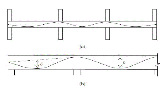
| Once the balanced load is determined, Eq. (4) calculates the prestressing force for each span. For frames with multiple spans and loadings, the highest prestressing force of the individual spans is used for all spans. To achieve the same balanced load for each span, the tendon profile is adjusted. A parabolic tendon profile is assumed for the load balancing as shown below in Fig.(5)(a), and (b) illustrates the definition of the tendon drape. The tendon profile has maximum eccentricities at the intermediate supports to counteract the negative moment and maximum sags at the midspan to counteract the positive moments. The eccentricity at the end supports must be zero, except when there is a cantilever, in which case, the eccentricity and slope of the profile must be zero at the end of the cantilever[9]. |
 |
| Once the prestressing force has been calculated, the number of tendons needed to achieve this force is determined. The required force is divided by an effective force in the strands. The effective force is used to account for the loss of force in the prestressing due to the relaxation of the steel and creep and shrinkage of the concrete.Then, the slab can be analyzed for the unbalanced load using the equivalent frame method. |
| Design moments for statically indeterminate post-tensioned members are determined by combining frame moments due to factored dead and live loads with secondary moments induced into the frame by the tendons. The load balancing approach directly includes both primary and secondary effects, so that for service conditions only “net loads” need be considered. |
| At design flexural strength, the balanced load moments are used to determine secondary moments by subtracting the primary moment, which is simply (F× e) where (e) is the eccentric, at each support[1]. An efficient design approach would be to analyze the equivalent frame under each case of dead, live, balanced, and lateral loads, and combine the cases for each design condition with appropriate load factors[1]. |
VI. PRESTESSED WAFFLE-SLAB LIMITATIONS |
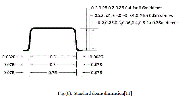
| Section (8.11) of ACI-code states that the concrete joist construction that dos not conform to the dimensional limitations most be designed as slab and beams. The limitation include that the ribs at least 100mm wide, spaced not more than 750mm clear, and for a depth not more than 3.5 times minimum width[7].Also when permanent burned clay or concrete tile fillers of material having a compressive strength at least equal to ' c f in the joists are used, the top slab thickness shall be not less than one-twelfth the clear distance between ribs, nor less than 40mm[7], |
| For slabs prestressed with unbonded tendons, a minimum average prestress of 0.9MPa is required by ACI 318M-11 Section (18.12.4) and a maximum average prestress of 2MPa is recommended by ACI-ASCE Committee 423. Average prestress is defined as the final prestressing force after losses divided by the total cross-sectional area of the concrete. The minimum value limits excessive tension andcracking, while the maximum value limits excessive elastic shortening and creep. |
| Minimum nonprestressed reinforcement requirements are laid out in ACI 318M-11 Section 18.9. In positive moment areas where computed tensile stress in concrete at service load exceeds 0.17 |
 |
| where the value of fy shall not exceed 420 MPa. Bonded reinforcement shall be uniformly distributed over precompressed tensile zone as close as practicable to the extreme tension fiber. Bonded reinforcement required shall be distributed between lines that are 1.5h outside opposite faces of the column support. At least four bars or wires shall be provided in each direction. Spacing of bonded reinforcement shall not exceed 300 mm. |
| In negative moment areas at column supports, the minimum area of bonded reinforcement Asin the top of the slab in each direction shall be computed by |
 |
| where Acf is the larger gross cross-sectional area of the slab-beam strips in two orthogonal equivalent frames intersecting at a column in a two-way slab. |
| In positive moment areas, minimum length of bonded reinforcement shall be one-third the clear span length, ln, and centered in positive moment area. In negative moment areas, bonded reinforcement shall extend one-sixth the clear span, ln, on each side of support. |
VII. SHEAR |
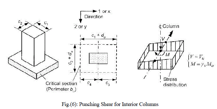
| There are two types of shear commonly checked: beam shear and punching shear. Beam shear creates diagonal cracking failure along the plane of principal tension. Beam shear rarely creates a problem in slabs because the plane of principal tension islarge and it is unlikely the whole plane will shear off[9]. Therefore, beam shear will be ignored in this paper. Punching shear occurs at the columns supporting the slab. Diagonal cracking failure creates a truncated pyramid-shaped or cone-shaped surface which “punches” through the slab.ACI 318M-11 defines the nominal punching shear capacity of concrete as |
 |
 |
 |
 |
VIII. THE DESIGN PROCESS |
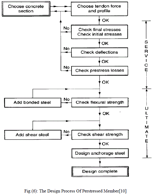
| Figure (7) illustrates the sequence of steps in the design of a post-tensioned member. For completeness, it includes the calculations relating to deflection, shear strength and ultimate flexure. |
| In post-tensioning, until calculations are carried out, it is not obvious whether the serviceability or the ultimate strength state, or both, are critical. Therefore, the serviceability checks for stresses and deflection are an essential part of the design. At the serviceability state, the stresses in the concrete are required to be within specified limits in compression and in tension, both at the time of prestressing with a minimum of load (initial stage) and in the long term under full applied load (final stage). If the serviceability state is satisfactory then the calculations proceed to considerations of the ultimate strength. Serviceability calculations follow the classical elastic theory, where stress is proportional to strain and the compression block is triangular. Bonded steel can be allowed for in calculating the moment of inertia of the section, by replacing it with an equivalent area of concrete at an appropriate value of the modular ratio. In designing post-tensioned floors, however, the normal practice is to take the gross concrete section and ignore bonded steel in calculating the section moduli. The area of tendon ducts is not normally deducted in the design of floors, though ACI 318 requires the effect of loss of area due to open ducts to be considered. Ducts may be open where access to a tendon is required after concreting, such as at couplers or where tendons are to be stressed from open pockets at the top of a floor.[10] |
 |
IX. PARAMETRIC STUDY |
 |
 |
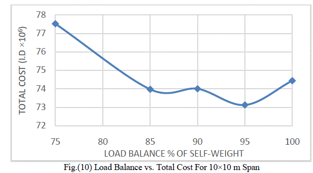
| Figure (10) shows the variation of the load balance with the total cost. It may be noted from this Fig. that the 90% balance load give minimum cost. |
 |
 |
 |
 |
X.CONCLUSIONS |
| 1- Span to depth ratio 1/23 to1/25 give an economic slab cost. |
| 2- Using minimum slab thickness give you minimum cost and weight. |
| 3- Using 750*750 dome with 150mm rib giving minimum cost and weight. |
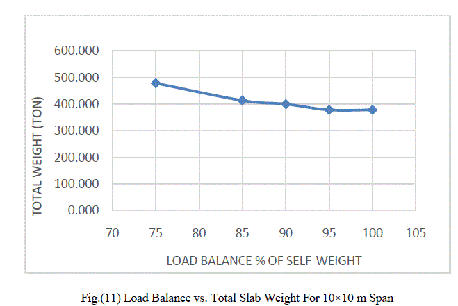
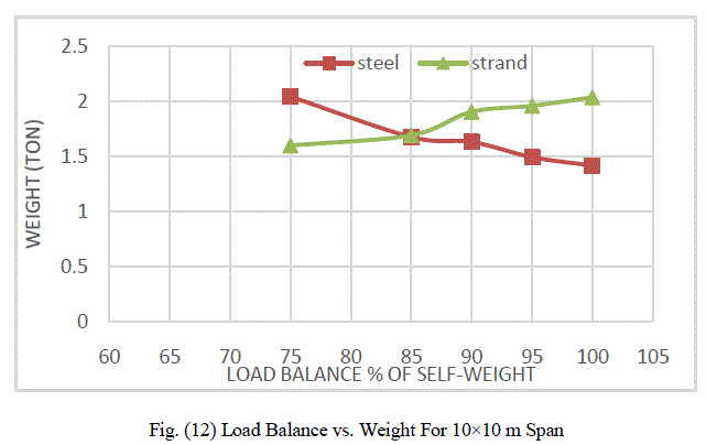
| 4- When increase balance load, slab thickness, steel weight and total weight decrease, tendon weight increase. |
| 5- The 95% balance load give minimum cost. |
| 6- For span more than 14 m it is repaired to use more than minimum slab thickness because the maximum dome depth is 500 mm which will increase total weight and cost. |
| 7- For span less than 6m, total depth available is more than required because minimum dome depth is 200mm, which will increase total weight and cost. |
References |
|