ISSN ONLINE(2319-8753)PRINT(2347-6710)
ISSN ONLINE(2319-8753)PRINT(2347-6710)
W.GiftonKoil Raj1, T.AmalSeba Thomas2
|
| Related article at Pubmed, Scholar Google |
Visit for more related articles at International Journal of Innovative Research in Science, Engineering and Technology
Wingtip vortices are strongly associated with induced drag for a three-dimensional wing. So it is important to neglect the wingtip vortices in order to reduce the induced drag. The drag breakdown of a typical transport aircraft shows that the lift-induced drag can amount to as much as 40% of the total drag at cruise conditions and 80– 90% of the total drag in take-off configuration. One way of reducing lift-induced drag is by using wingtip devices. By applying biomimetic abstraction of the principle behind a bird’s wingtip feathers, we study spiroid wingtips, which look like an extended blended wingtip that bends upward by 360 degrees to form a large rigid ribbon.In this paper a configuration of different winglets are studied. A model composed of wing of boeing-737 is designed using CATIA and also the spiroid winglet are designed and attached with a boeing 737 wing using CATIA. Then the modelled wing is meshed using ICEM-CFD. The meshed model will be analysed using ANSYS FLUENT. Finally the percentage decrement of wingtip vortices is calculated using the analysis results.
Keywords |
| Vortices, Induced drag, Spiroid winglet, CATIA, ICEM-CFD, ANSYS FLUENT. |
INTRODUCTION |
| Wingtip devices are usually intended to improve the efficiency of fixed-wing aircraft. There are several types of wingtip devices, and although they function in different manners, the intended effect is always to reduce the aircraft's drag by partial recovery of the tip vortex energy. Wingtip devices can also improve aircraft handling characteristics and enhance safety for following aircraft. |
| Such devices increase the effective aspect ratio of a wing without materially increasing the wingspan. An extension of span would lower lift-induced drag, but would increase parasitic drag and would require boosting the strength and weight of the wing. At some point, there is no net benefit from further increased span. There may also be operational considerations that limit the allowable wingspan. Wingtip devices increase the lift generated at the wingtip by smoothing the airflow across the upper wing near the tip and reduce the lift-induced drag caused by wingtip vortices, improving lift-to-drag ratio. This increases fuel efficiency in powered aircraft and increases cross-country speed in gliders, in both cases increasing range. |
| In aeronautical engineering, drag reduction constitutes a challenge and there is room for improvement and innovative developments. The drag breakdown of a typical transport aircraft shows that the lift-induced drag can amount to as much as 40% of the total drag at cruise conditions and 80–90% of the total drag in take-off configuration. One way of reducing lift-induced drag is by using wingtip devices. By applying biomimetic abstraction of the principle behind a bird’s wingtip feathers, we study spiroid wingtips, which look like an extended blended wingtip that bends upward by 360 degrees to form a large rigid ribbon. |
| From an aerodynamicist’s point of view, the main motivation behind all wingtip devices is to reduce lift-induced drag. Aircraft manufacturers are under increasing pressure to improve efficiency due to rising operating costs and environmental issues, and this has led to some innovative developments for reducing lift-induced drag. Several different types of wingtip devices have been developed during this quest for efficiency and the selection of the wingtip device depends on the specific situation and the airplane type |
| Wingtip vortices are circular patterns of rotating air left behind a wing as it generates lift. One wingtip vortex trails from the tip of each wing. Wingtip vortices are sometimes named trailing or lift-induced vortices because they also occur at points other than at the wing tips. Indeed, vorticity is trailed at any point on the wing where the lift varies spanwise it eventually rolls up into large vortices near the wingtip, at the edge of flap devices, or at other abrupt changes in wing platform. |
| Wingtip vortices are associated with induced drag, the imparting of downwash, and are a fundamental consequence of three-dimensional lift generation. Careful selection of wing geometry as well as of cruise conditions, are design and operational methods to minimize induced drag. |
| Wingtip vortices form the primary component of wake turbulence. Depending on ambient atmospheric humidity as well as the geometry and wing loading of aircraft, water may condense or freeze in the core of the vortices, making the vortices visible. |
III. WINGLETS |
| The term "winglet" was previously used to describe an additional lifting surface on an aircraft. Another potential benefit of winglets is that they reduce the strength of wingtip vortices, which trail behind the plane and pose a hazard to other aircraft. Minimum spacing requirements between aircraft operations at airports is largely dictated by these factors. Aircraft are classified by weight (e.g. "Light," "Heavy," etc.) because the vortex strength grows with the aircraft lift coefficient, and thus, the associated turbulence is greatest at low speed and high weight. The drag reduction permitted by winglets can also reduce the required takeoff distance. |
| Winglets and wing fences also increase efficiency by reducing vortex interference with laminar airflow near the tips of the wing, by 'moving' the confluence of low-pressure (over wing) and high-pressure (under wing) air away from the surface of the wing. Wingtip vortices create turbulence, originating at the leading edge of the wingtip and propagating backwards and inboard. This turbulence delaminates the airflow over a small triangular section of the outboard wing, which destroys lift in that area. The fence/winglet drives the area where the vortex forms upward away from the wing surface, since the center of the resulting vortex is now at the tip of the winglet. |
| Winglets reduce wingtip vortices, the twin tornados formed by the difference between the pressure on the upper surface of an airplane's wing and that on the lower surface. High pressure on the lower surface creates a natural airflow that makes its way to the wingtip and curls upward around it. When flow around the wingtips streams out behind the airplane, a vortex is formed. These twisters represent an energy loss and are strong enough to flip airplanes that blunder into them.Winglets produce an especially good performance boost for jets by reducing drag, and that reduction could translate into marginally higher cruise speed. But most operators take advantage of the drag reduction by throttling back to normal speed and pocketing the fuel savings. |
IV. BIOMIMETICS FROM BIRDS’ WINGTIP FEATHERS TO WINGLETS ON AIRPLANES |
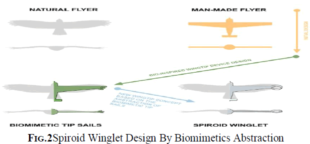
| In this manuscript we tackle the problem of lift-induced drag and tip vortices mitigation by looking at the analogous problem in nature. Birds’ wingtip feathers with their large variety in morphology are biological examples to examine. It can be seen how the wingtip feathers of different birds are bent up and separated like the fingers of a spreading hand. This wingtip feathers slotted configuration is thought to reduce the lift-induced drag caused by wingtip vortices. Tucker showed for the first time that the presence or absence of these tip slots has a large effect on the drag of birds. He found that the drag of a Harris hawk gliding freely at equilibrium in a wind tunnel increased markedly when the tip slots were removed by clipping the primary feathers. The slots also appear to reduce drag by vertical vortex spreading, because the greater wingspan and other differences in the bird with intact tip slots did not entirely account for its lower drag. |
| It is worth mentioning that we do not use any winglet design or optimization criteria when designing the proposed spiroid winglet. Instead, it is built in a very heuristic way, by just splitting the wingtip with two winglets and joining them with an additional horizontal segment. In order to smoothen the transition between the wing and the spiroid winglet, a small joining section is added. Then, the spiroid winglet is attached to the clean wing and an extensive campaign of numerical simulations using the clean wing and the wing with the spiroid winglet is conducted. At this point, it becomes clear that if, by using this simple biomimetics approach we are able to obtain some benefit in terms of lift-induced drag reduction, wingtip vortices intensity reduction and lift enhancement, the approach proves to be worthwhile and further wingtip design and optimization deserves to be carried out. |
 |
V. LIFT AND DRAG OF FINITE SPAN WINGS |
| Finite span wings generate lift due to the pressure imbalance between the bottom surface (high pressure) and the top surface (low pressure). However, as a by product of this pressure differential, cross flow components of the velocity are generated. The higher pressure air under the wing flows around the wingtips and tries to displace the lower pressure air on the top of the wing.. These structures are referred to as wingtip vortices and very high velocities and low pressure exist at their cores. These vortices induce a downward flow, known as the downwash and denoted by w. This downwash has the effect of tilting the free-stream velocity to produce a local relative wind, which reduces the angle of attack(α) that each wing section effectively sees; moreover, it creates a component of drag, the lift-induced drag. |
| After having introduced the notion of lift-induced drag, we can now write the equation for the total drag of a wing as the sum of the parasite drag (which is basically the sum of the skin friction drag and pressure drag due to flow separation) and the induced drag, or in non-dimensional form: |
| CD=CD0+CDind (1) |
| Where CD0 is the drag coefficient at zero-lift and is known as the parasite drag coefficient, which is independent of the lift. The second term on the right-hand side of Eq. (1) is the lift-induced drag coefficient CDind, defined by |
 |
| In Eq. (2), CL is the wing lift coefficient, AR the wing aspect ratio and e is the Oswald efficiency factor (which is a correction factor that accounts for the difference between the actual wing and an ideal wing having the same aspect ratio and an elliptical lift distribution) or wingspan efficiency. Eq. (2) can be rewritten as, |
| Where we have replaced 1/(πe AR) by K, a factor which clearly depends on the wing geometry. Substituting Eq. (3) in Eq. (1) we obtain, |
VI. WING SELECTION |
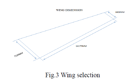
| The wing selected for our work is the wing of Boeing 737 |
| Aircraft: Boeing-737 |
| Wing Span: 28350mm |
| Wing Taper Ratio: 4.575 |
 |
VII. AIRFOIL SELECTION |
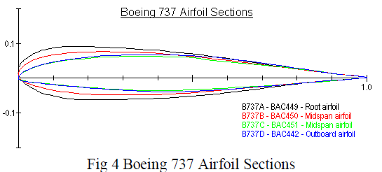
| Root: b737a-il |
| Mid span: b737b-il, b737c-il |
| Tip: b737d-il |
 |
| The computational steps in this project consist of three stages. The project will begin from preprocessing stage of geometry setup and grid generation. The geometry of the model was drawn using CATIA. The meshing will be generated by ICEM CFD. The second stage is computational simulation by ANSYS using finite volume approach. Finally is the post-processing stage where the aerodynamic characteristics of the winglets are to be found. At the winglet wall and then incrementally increase up to the bullet shaped boundary wall. The sizing function scheme will help to reduce the computational time. |
| The numerical simulation by the ANSYS will be made after the completion of the mesh generation. The ANSYS formulation, boundary condition, solution control parameter, and material properties are to be defined. After the parameter specified the model was initialized. The initializing and iteration process stops after the completion of computations. The results obtained will be examined and analyzed. |
VIII. MODELLING OF WING AND WINGLET |
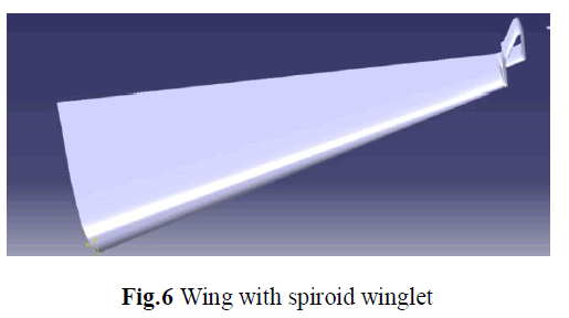
| The wing is designed with CATIA v5 using the root and tip co-ordinates of boeing-737 aircraft and extruded using the using the wingspan. |
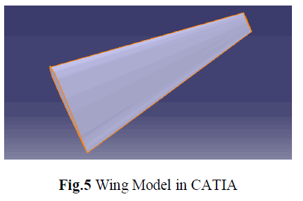 |
| The pad tool is used mostly to create extruded features. Wings of all the models were extruded using pad tool. The winglets were drawn using rib tool, plane definition tool, line tool, inflation tool, rotate tool, measure tool, and scale tool. |
| ïÃâ÷ The wing has been designed by using the catia v5 software. |
| ïÃâ÷ The coordinates of the wing imported into the catia from excel. |
| ïÃâ÷ Then root and tip airfoils are connected using the command multi section solid |
| ïÃâ÷ Then the winglet has been drawn by using the rib |
| ïÃâ÷ Then the surfaces extracted from the solid by using the extract command. |
 |
TEST SECTION |
| ïÃâ÷ Then the test section has been drawn using the extrude |
| ïÃâ÷ Then the inlet and outlet are formed by using the fill |
| ïÃâ÷ Then the design saved in the igs format. |
Test section details |
| Inlet Area 285×106mm2 |
| Outlet Area 285×106mm2 |
| Length 15000mm |
| Volume of test section 4275×109mm3 |
 |
| Meshing was made using ANSYS ICEM CFD. The CAD drawings made using CATIA was imported to ICEM CFD. The imported files are in *stp format. The parts are created in geometry phase. Parts named as INLET, OUTLET, WALL, WING and BODY. Meshing was made using unstructured tetrahedral mesh tool. Then the solver option and output options were converted to ANSYS CFX formats and exported to *.cfx format. |
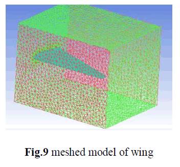 |
Mesh details |
| Element Volume Ratio |
| Min: 1 |
| Max: 6622.1 |
| Number of Nodes 109555 |
| Number of Elements 566429 |
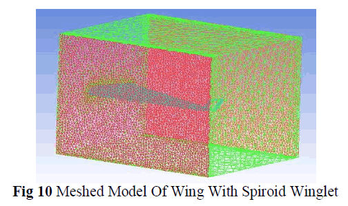 |
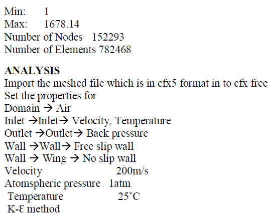
Mesh details |
| Element Volume Ratio |
 |
X.NUMERICAL RESULTS AND DISCUSSION |
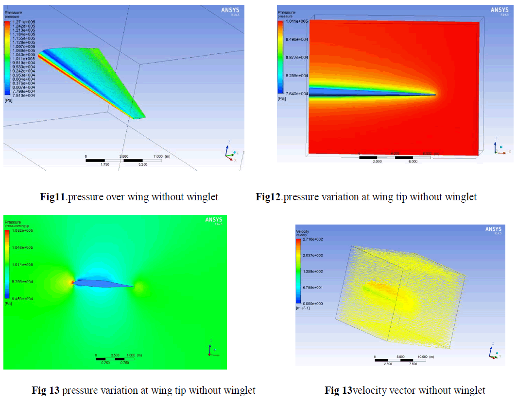 |
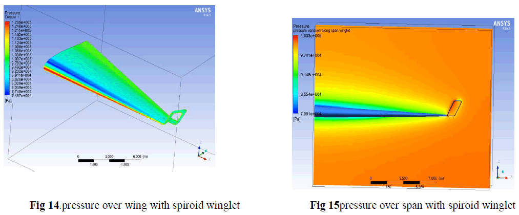 |
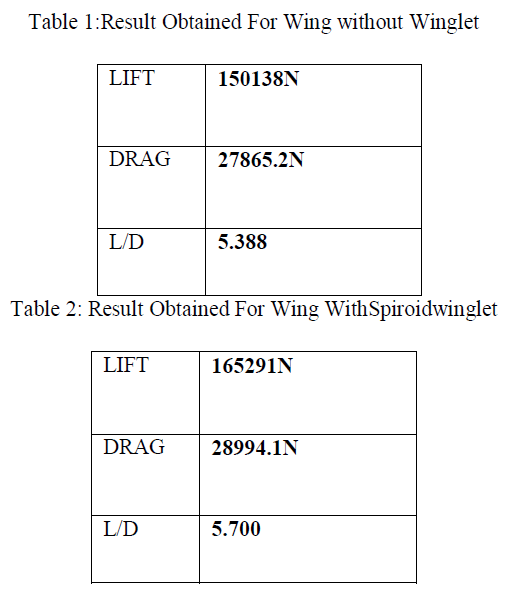 |
XI. CONCLUSION |
| In the aeronautical field reducing drag is a major challenge. The drag breakdown of a typical transport aircraft shows that the lift-induced drag can make-up as much as 40% of the total drag at cruise conditions and 80-90% of the total drag in the take-off configuration. In this for reducing inducing induced drag we used spiroid winglet. If lift to drag ratio increases the drag will reduce here in the spiroid winglet the lift to drag ratio increases than wing without winglet so the spiroid winglet reduces the vortices. |
References |
|