ISSN ONLINE(2319-8753)PRINT(2347-6710)
ISSN ONLINE(2319-8753)PRINT(2347-6710)
| Mohd. Sadaf Sr. Engineer (Pipelines), Indian Oil Corporation Limited, Allahabad, U.P., India |
| Related article at Pubmed, Scholar Google |
Visit for more related articles at International Journal of Innovative Research in Science, Engineering and Technology
The cross country underground pipelines are given Cathodic Protection (C.P.) in addition to epoxy coatings to check any corrosion due to the development of a ‘Pipe-to-Soil Potential’(PSP) in the event of direct contact of the pipe with ground. We are having ‘Test Lead Points’ (TLPs) at regular intervals of around 2 kilometres to check & periodically record the local PSP with the help of a Cu/CuSO4 half cell. If any abnormality in the PSP at a TLP is observed, it’s an indication that the pipeline coating is damaged nearby. This is an established industrial practice. But its scope is limited to checking the health of pipeline coating only, while detection of pilferage location remains a challenge. This paper suggests a methodology to detect pilferage/theft in the pipeline & its location with the help of PSP readings.
Keywords |
| Cathodic Protection, Pilferage Detection, Underground Metallic Pipelines, Pipe- to- Soil Potential, Leak Detection System |
INTRODUCTION |
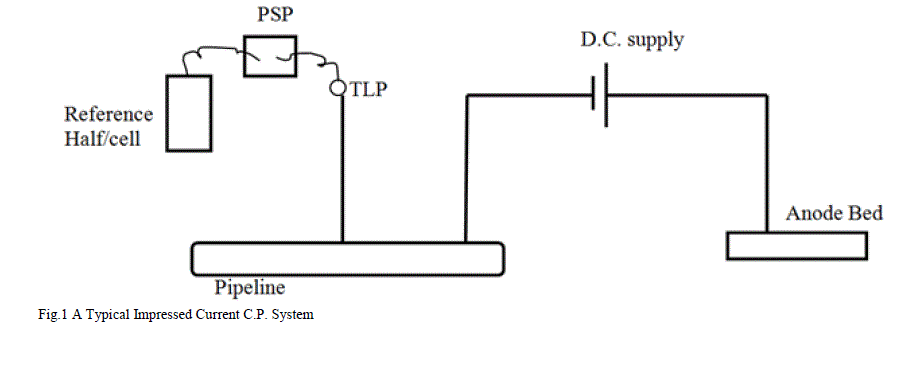
| Impressed Current Cathodic Protection System (Fig.1) gives a negative potential to the buried pipe with respect to the anode bed. A PSP of -1.5V to -0.85V with respect to Cu/CuSO4 half cell is maintained throughout the pipe length. For this soil resistivity tests are also carried out to maintain proper DC supply. Pipe-to-Soil Potential (PSP) surveys are carried out periodically through the TLPs to check that the PSP value is maintained within the range. If any abnormality is observed in PSP value at a TLP, excavation is carried out in the nearby area to check at which point the coating has got damaged leading to higher current drain & abnormal potential drop. But so far, no methodology for detecting pilferage/leakage in the pipeline has been adopted in the industry that is cheap, reliable, & may be maintained without outsourcing. The conventional Leak Detection Systems (LDS) detects pilferage only when pumping through the pipeline is in progress (but it can’t sense if petroleum product is being drained by the thieves at a low rate). As a routine practice during shutdown, if Incoming /Outgoing pressure in the pipeline drops suddenly, we get to know that pilferage has been done in that section (stretch of hundreds of kilometres) that has sectionalising valves at about every 50 kilometres. |
II. INTRODUCTION |
| The cross country underground pipelines are given ‘Impressed Current Cathodic Protection System’ in addition to epoxy coatings to check any corrosion due to the development of local electrochemical cells due to a pipe-to-soil potential (PSP) in the event of direct contact of the pipe with ground. We are having ‘Test Lead Points’ (TLPs) at regular intervals of a few kilometres to check & periodically record the local PSP with the help of a Cu/CuSO4 half cell[1]. If any abnormality in the PSP at a TLP is observed, it’s an indication that the pipeline coating is damaged nearby. |
 |
| One of the most challenging matters for pipeline department is early detection of pilferage attempt. At some places a flow differential based Leak Detection System (LDS) is in place that compares the outgoing flow rate of an upstream pumping station to that of the downstream pumping station to detect a pilferage/leakage. But its results are not accurate & the location of pilferage/leakage is often misleading. So, one has to go for manual patrolling of hundreds of kilometres on getting the information of pilferage in a section (stretch of hundreds of kilometres) that is a time taking job & not always fruitful. |
| I would like to propose a methodology for detecting the region of pilferage within 1-2 kilometres of the actual site. So that the time & energy wasted in manual patrolling, that is being done after pilferage information, would be drastically reduced. |
III. DEVELOPMENT |
| As we know that any damage to the coating is reflected in the PSP reading, so whenever there is a pilferage, & coating is removed to fix a clamp on the pipeline & soil is backfilled (to hide the clamp), the pipe comes in direct contact of the ground. That must increase the drain current & must be clearly reflected in the PSP reading. We may go for three options: |
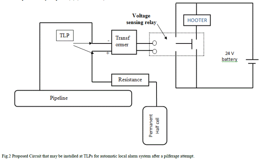
| A. We may build such a system at each TLP that if the PSP suddenly falls due to removal of coating (pilferage) an alarm may start blowing that will not only frighten the thieves but also alert the villagers nearby. The design for this system is elaborated in this paper. |
| B. In case of leak detection by conventional LDS during pumping we shall directly reach the TLPs (at every 2 km) in the indicated section through nearby roads (no need to walk through the entire length through the fields) & take PSP readings & compare with the last PSP readings. Any abnormality at any TLP/TLPs should indicate the location of pilferage (within 1-2 km). |
| C. In the case of routine information of pilferage during shutdown, right after sectionalizing the pipeline by closing sectionalizing valves, we shall reach the TLPs in the section & take PSP readings & compare with the latest readings. Any abnormality at any TLP/TLPs should indicate the nearby location of pilferage. |
| If we could develop this system then probably we may get leak detection/pilferage even if the leakage is small & flow is going on or shutdown. |
IV. DESIGN |
| A. A Simple circuit for option (A) (local alarm)*: |
 |
| B. Components: |
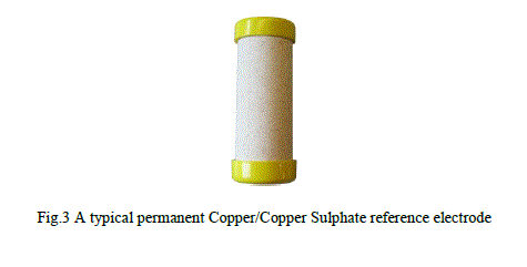
| 1.) Permanent Half Cell: It has to be installed at the TLPs. The Potential difference between the lead through TLP & Half cell shall be the input ‘sensing’ voltage for the ‘Voltage-sensing relay’. |
 |
| 2.) Voltage-sensing relay: The Schneider Electric make, model 831 ‘Voltage Sensing Relay’[2] that operates above/below the set range of input (sensed) voltage needs an input DC voltage of 24V & the power consumption is around 1 watt that means a current of around 40mA. From its specifications it seems that it can sense an undervoltage up to 6V. So, I have put a transformer between the TLP & Voltage-sensing relay to step-up the voltage from 0.85V to 6.5V so that it may be ‘sensed’. However, a relay with the ‘sensing’ voltage in the range of 1V may also be available with some other companies. |
 |
| 3.) Hooter: The hooter(make ABS-III) has an input rating of 24V DC & 350 mA & output of 110dB (over 1 km range) |
| 4.) Battery: As the circuit is opened all the time, except in the case of an under-voltage due to pilferage & subsequent grounding of the exposed (coating removed & clamp fitting followed by backfilling) pipe, there is no continuous power consumption through the battery. A 24V, 12 Watt Battery (dry cell) would serve the purpose. |
| Note: All the components used in the circuit are available in the market with different suppliers & ratings. I have taken specifications of those known to me. |
| C. Working: The lower limiting voltage for ‘Voltage Sensing Relay’ is set at 0.3V (this value was observed near a TLP where damaged coating was found). The PSP is maintained in the range of -1.5V to -0.85V with respect to Cu/CuSO4 half cell as per industrial practice [1]. As the pilferage attempt is made & the drain exposed pipe surface is covered, the PSP falls below the minimum level i.e. 0.3V, the relay gets charged & switches the secondary circuit that has a DC hooter that starts blowing that is audible up to 2 kms. far locations, mostly villages. |
| D. Power consumption: The only area of continuous power consumption is between the lead of TLP & the permanent half cell (i.e. in the primary coil of the transformer). But that should not be a problem as the permanent half cells are already in use at some oil companies for data logging & the current flows from the ‘cell’ to the ‘pipe’, so it aids the C.P. system & does not oppose it so there won’t be any disturbance in the Cathodic Protection system in place except a little increase in current density. |
 |
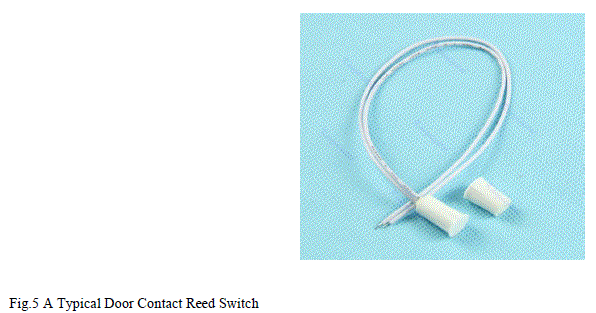
| A current of the order of a few milliamps (mA) has to be provided by the half cell depending upon the resistance put between the half-cell & the pipe (adjustable). This power consumption (in transformer) won’t be there if a ‘voltage sensing relay’ with ‘sensing voltage’ range 0.3V to 1.5 V is used. That would ensure that transformer is not required & hence no current is drawn through the permanent half cell. The power required by the hooter & the relay (total of 400 mA) shall be given by the 24V battery only during the time of pilferage. However, if these things are installed, a small box enclosure has to be built to cover the system. A simple contact switch/ sensor shall also be put there that shall generate alarm if anybody tries to open/ damage the door of the box |
 |
V. CONCLUSION |
| The system proposed here is very effective in detecting pilferage/theft in the underground cathodically protected petroleum product pipelines and as & the drain current due to this system flows from the ‘half cell’ to the ‘pipe’, so it aids the C.P. system & does not oppose it so there won’t be any disturbance in the Cathodic Protection system in place except a very little increase in current density. If somebody finds the design elaborated here to be a little costly affair, he may start with the options ‘B’ & ‘C’ suggested above (under the heading DEVELOPMENT). Once he is satisfied with those options, he may go for the system detailed in this paper. |
ACKNOWLEDGMENT |
| I am extremely thankful to my controlling officer who believed in my idea & spared me some time from my routine assignments to do the research work. |
References |
|