Research & Reviews: Journal of Chemistry
e-ISSN: 2319-9849
e-ISSN: 2319-9849
Saudi Aramco, Dhahran, Saudi Arabia
Received date: 24/10/2018 Accepted date: 06/11/2018 Published date: 11/11/2018
Visit for more related articles at Research & Reviews: Journal of Chemistry
Emulsion drilling fluids have shown improved performance compared to water based fluids in the field. However, emulsion stability which is indicated by the resistance of the chemical emulsifier against contaminant (anhydrite, cement, sodium chloride, ions of calcium and magnesium and others) is always a concern. Concentration will vary from one emulsifier to another depending on the chemical composition of the emulsifier. To the best of authors’ knowledge this is the first paper that details different chemistry of emulsifiers used in oil based drilling fluids. The paper details also basics about emulsifier interaction with oil and water phases as well as the factors we need to consider in emulsifier selection. Emulsion types and stability are also investigated in this paper. Different options of emulsifiers are also detailed with examples of oil based fluids utilized for typical drilling operations.
Emulsion, Emulsifiers, Drilling fluids.
Oil based muds were initially developed to address the problems of reactive shale, high temperature wells, contaminants, and stuck pipe. They also offer qualities to control formation damage, and obtain native-state cores. Oil muds are suitable for drilling through water sensitive clays, as they can prevent water invasion into the shale via a proper control of the mud salinity during the formulation. The salinity should be maintained such that it prevents water transport into the shale which can lead to hydration and swelling, and at the same time avoid severe water withdrawal from the shale, which can lead to undesirable dehydration and hence shale destabilization. Additional advantage lies in maintaining the salinity just under saturation in the water phase of invert emulsions. This allows them, as well, to be used in drilling gauge holes through deep salt formations with minimum washouts without the need to worry about the salt leaching out, unlike the case with water-based mud.
Oil muds are in general more tolerant to high temperatures than water. This nature allows them to be applicable in drilling high temperature-high pressure wells, where water-based muds would break down, lose their viscosity and fluid loss control, and cause corrosion. The non-conductive nature of oils as an external phase of oil muds offers the quality of corrosion control as oil wets the metal surfaces blocking the corrosion cells from development. Besides, oil muds are unsusceptible to the growth of bacteria. This protection oil muds offer against corrosion, along with their high thermal stability and their ability to suspense weighting materials over long periods qualify them to be used as packer fluids.
Emulsifiers are special products added to the oil mud to be dispersible in the external oil phase, and to ensure emulsion stability of water internal phase under the extreme downhole conditions.
Emulsion is dispersion of liquid droplets into another liquid. These liquid droplets are referred to as internal phase. We could have 3 types of emulsion; water –in-oil, oil-in-water, and multiple or complex emulsions [1] (Figures 1-3).

Figure 1. Photomicrograph of water-in-oil-emulsion.

Figure 2. Photomicrograph of oil-in-water-emulsion.

Figure 3. Photomicrograph of multiple or complex emulsion.
In petroleum industry, the common emulsion is water in-oil emulsion. For this reason, oil-in-water emulsion are named reverse emulsion. Figure 3 shows multiple or complex emulsion where the continuous phase has suspended droplets and these droplets have smaller droplets suspended in them.
The criteria for Emulsion to occur are that we need to have differences in solubility between a continuous phase and an emulsified phase, we need to have intermediate agent (emulsifier) that have partial solubility in each phase (oil and water), and finally a source of energy such as mixer to form the emulsion.
Emulsifiers are surfactants that are partially soluble in water due to its hydrophilic part of polar end. The emulsifiers need to be partially soluble in oil due to their hydrophobic part or non-polar end.
The emulsifier will concentrate at the oil/water interface and it will form interfacial film that result in reducing interfacial tension (IFT) to allow dispersion and droplet emulsification. Generally emulsifiers could be organic acid or resins. For emulsifiers to be partially soluble in both emulsion phases, they need to have bipolar molecules i.e., polar and non-polar ends. At equilibrium, the emulsifier’s non-polar end will be extended into the non-polar oil phase and the polar end will be extended into the polar water phase [2].
Below in Figure 4 are some examples with bipolar molecules with polar ends of NH2, COOH, OH, NH, and O groups.

Figure 4. Bi-polar molecules.
The chemistry of the emulsifier will determine the type of emulsion. As a quick rule, the emulsion type can be classified based on the biggest volume fraction; water-in-oil emulsion if we have more oil and oil-in-water emulsion if we have more water.
Molecules with strong polar group interaction tend to form water-in-oil emulsion. Molecules with weaker polar group interaction tend to form oil-in-water emulsion. For fatty tail or alkyl group that is highly branced or contain rig structure, the force of interaction (London Dispersion Force) tend to be weaker compared to liner alkyl group. So emulsifiers’ with linear alkyl group will form water-in-oil emulsion. If fatty tail or alkyl group is not highly brached then we are going to have oil in water emulsion [3].
To determine the emulsion type, a simple test can be made. By placing small portion into two beakers; one with water and the other one with xylene. When we stir the mixture, if the emulsion is oil external it will disperse in the xylene. If it is water external it will dispers in the water quickly. Once we know the emulsion type we can do also a simple test to quantify the internal phase in the emulsion. This can be done by diluting the emulsion in a solvent (dispersing solvent such as water or xylene) in 2:1 ratio of solvent to emulsion. The diluted mixture is then subject to heating and centrifuge to separate phases utilizing graduated centrifuge tubes to measure each phase. Most of the time we have stable emulsion and adding de-emulsifier is required. Typical de-emulsifier could be a mixture of alkyl-substituted phenolic resin oxyalkylated with ethylene oxide, and an amine sulfonate. This method is more accurate for water-in-oil emulsion than oil-in-water emulsion. Water pH also can affect and determine emulsion type. At low pH typically we will have water-in-oil emulsion. At high pH values we will have oil-in-water emulsion [3].
Atlas Powder Company chemist William Griffin introduced the hydrophilic–lipophilic balance (HLB) for emulsifier classifica tion in 1949 [4]. In his paper, Griffin stated: “emulsifiers consist of a molecule that combines both hydrophilic and lipophilic groups and the balance of the size and strength of these two opposite groups is called HLB. For the purpose of convenience, the effective balance of these groups is assigned a numeric value”. Experimental work required to estimate the HLB value was also detailed in Griffin paper. He also provided details about HLB values for emulsifier’s mixture. The additive property is applied to provide the requirements of HLB values for oil mixtures. An illustration of the HLB scale is shown in Figure 5.

Figure 5. An illustration of HLB Scale.
Determining the HLB value of a surfactant was detailed in a later publication [4]. For nonionic surfactants, the HLB is calculated as follows:
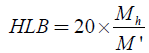
Where, Mh: is the molecular mass of the hydrophilic portion of the molecule. M: is the molecular mass of the whole molecule.
More recently introduced methods for calculating the HLB value for can be found in Ricardo et al. [5]. As an example, for the nonionic surfactant shown in Figure 6, the HLB value is 13.4 and therefore is expected to be hydrophilic (water soluble). This surfactant will help create oil-in-water emulsions. This is due to the presence of hydrophobic tail in the form of a hydrocarbon chain attached to a hydrophilic polar head groups. This enables this chemical to dissolve in both aqueous and non-aqueous fluids and to reduce the surface tension. A surfactant with this HLB value helps trap hydrocarbon-based fluids in water to form an emulsion with water as the continuous or external phase.

Figure 6. An example of a surfactant with a 13.4 HLB value.
Emulsion Stability
Some ions with high hydration energy such as Al+++, Fe+++, Cu++, Co++ can result in forming strong ionic interaction with the polar phase of emulsion system. The water surround these ions forming hydration sheath. The strength of this sheath is determined by the ion charge and its size. So for two ions of equal charges but different sizes, the smallest one will show a strong interaction.
Sometimes in the polar phase we could have mixed ions (anionic and cationic). Most of the cations are accompanied by anion forming hydrogen bonding. If mixed ions are not present, then the water (polar phase) will provide the counter-ion either as a hydronium or as hydroxyl ion. For non-polar phase, the force of attraction is less. London Forces of induction comes from electron orbital blending and are caused by the close approach of one atom of a molecule to another one. This type of orbital blending is controlled by Van Der Waals Radii [2].
Similar atoms or molecules (same charge) are repelled however if their momentum of velocity are high enough to overcome the repulsion they will combine instead of repulsion. Their center distance is the Van Der Waals Radius and it should be as minimum as possible to cause the combination and prevent repulsion. In non-polar phase, London Forces are weak. When we have highly brached molecules the interactions are reduced so the strength is less. For example, Sorbitan Mono-Oleate emulsifier can accumulate more alkyl units than the highly branced Naphtoic acid causing Sorbitan Mono-Oleate emulsifier to form more stable emulsion [2].
The droplet size can also contribute to stability of emulsion. As droplet size decrease the more stable the emulsion will be. Droplet size larger than 0.1 um is called macro emulsion. Droplet size less than 10 nm called micro emulsion. We will have this type of micro emulsion if the internal phase and external phase have low interfacial energy, Fine solids can stabilize emulsion only if their size is smaller than emulsion droplet. These fine solids could be clay particles, sand, or minerals. The droplet size in emulsion is determined by IFT, shear, emulsifier concentration, and presence of solids.
The viscosity of emulsion could be greater than the viscosity of the internal phase or external phase due to droplet accumulation. Bulk viscosity can be measured using rotational viscometer. The viscosity of the fluid at the oil/water interface is the interfacial viscosity. For stable emulsion, the interfacial viscosity should be high or the IFT (Interfacial tension) should be low (Figure 5). Stable emulsion means low rate of oil drainage from the emulsified water droplet in case of water-in-oil emulsion. Interfacial viscosity depends on type of oil used (paraffinic, etc.), composition and pH of water, temperature, mixing duration, and emulsifier type and concentration.
Adding fine solids will stabilize the interfacial film and will increase the interfacial viscosity. Fine solids will prevent the droplet from accumulation or coalescence. In the case of water-in-oil emulsion, as the aromatic content of oil increase its wettability to the solids increase thus increasing the emulsion stability. Oil with high cloud point typically can form a more stable and tighter emulsion compared to oil with low cloud point.
The solids we put in oil based mud need to have the right wettability. Contact angle measurement need to be measured. If the contact angle is more than 90 degree the solid is oil wet. If the angle is more than 90 it is water wet. Solids need to show wettability in both phases (oil and water) to form stable and tight emulsion. The oil wet solids will stabilize the water-in-oil emulsion because they will partition into the oil phase preventing coalescence of water droplets. Similarly, the water wet solids will stabilize oil-in-water emulsion. Water wet solids can be converted to oil wet solids by utilizing polar organic compounds coating. The solids need to be added before emulsion is made stable.
Mixing the emulsified fluid would result in production of larger emulsion size and increased viscosity under constant temperature and pressure. Emulsion will have equilibrium transfer of internal phase solvent between emulsifier aggregates. When temperature increase this transfer of phase solvent will increase in the emulsion aggregates. The temperature could increase to a higher level so the internal phase will be depleted from the solvent and same thing for the external phase it will be depleted from the solvent. This differential rate of solvent loss between the internal and external phase will indicate overall system stability.
Oil Based Drilling Fluid Additives
Below are the main components (additives) we use to formulate oil based drilling fluids:
• Primary emulsifiers are the result of the reaction between lime and fatty acids. They are used to emulsify water into oil in the oil-based fluid and stabilize the emulsion. They also act as wetting agents, preventing solids from getting water wet during the emulsion process. Calcium soaps are the primary emulsifiers used in the oil muds.
• Secondary emulsifiers are typically polyamides or imidazolines. They are very strong oil wetting products that oil wet solids prior to emulsion formation.
• Organophilic lignites are lignites that are treated with amine to become oil dispersible. They help in the water emulsification at high temperatures, and controlling fluid loss by plugging.
• Asphaltic additives are additives used as treatment for fluid loss. They consist of gilsonite or asphalt derivatives. The gilsonite derivatives have higher temperature stability than those of asphalt.
• Organophilic gellants are additive that are made from bentonite, hectorite, or attapulgite, as viscosity builders treated with an amine to become oil dispersible. Bentonite is usually used for temperatures below 350°F, while Hectorite is used for temperatures higher than 350°F.
• Wetting agents are supplemental additives that are utilized to effectively oil wet solids that become water wet by replacing the water layer with oil layer around the drill solids.
• Polymeric viscosifiers are additives used to enhance the viscosity of the mud, especially at high temperatures, where the viscosity effect of the organophilic gallant is reduced.
• Rheological modifiers are basically fatty acids with low molecular weight that are used to minimize the sag of barite down the hole without increasing the total mud viscosity.
• Weighting agents such as barite, manganese tetroxide, and hematite are additives used to enhance the density of the mud. Hematite and Manganese Tetroxide have higher specific gravity, and thus they can achieve the same mud weight achieved by barite with less solids.
Base Oil Types
There is a variety of oils that can be used as base-oil for oil muds. Each of these oils possess different properties; flash point, aniline point, viscosity, and aromatic content, which would significantly affect the overall physical properties of the mud.
Diesel and crude oil are the most commonly used oils to formulate oil-based mud. Environmental concerns and the resulting regulations, however, have limited their use in some conditions. Mineral oils and synthetic fluids were introduced as replacement. Below, the main types of base oils used for oil drilling fluids are presented.
• Crude oils are used when refined oils, such as diesel, are not sufficiently available. They have lower flash points and aniline points compared to refined oils. The low flash point which makes them more likely to catch fire. The low aniline point, on the other hand, indicates the high potential for the oil to deteriorate the rubber parts of the circulating system.
• Refined oils such as diesel or kerosene are the most commonly used base-oil for oil based drilling fluids. They have a very high aromatic content, which makes them more toxic than crude oils, but offer a less base viscosity than that of the crude oil.
• Mineral oils have lower aromatic content than diesel, which makes them less toxic and more environmentally acceptable. They are also safer to use at high temperatures as they have higher flash points. Mineral oils are of low viscosity compared to diesel and do not contain surfactants that can change the formation’s wettability.
• Synthetic fluids are non-petroleum hydrocarbons that act like petroleum hydrocarbons. They are biodegradable, which makes them very environmental friendly. They show low stability at high temperatures, they do not react with shale rapidly neither with hydration nor dehydration, and they are also of high viscosity at ambient temperatures.
Emulsifiers Used for Drilling Fluids
Below is a list of different options of emulsifier blends used for drilling fluids:
Option 1. Ethoxylated Phenol and Nonylphenol in water solvent. It is a mixture of water and rest is the Ethoxylated P-Nonyl phenol. This emulsifier will enhance the effectiveness of other drilling fluid additives such as lignosulfonate and others. It can also coat formulation cuttings and wellbore to prevent hydration.
Option 2. Sodium soap of modified Tall Oil Fatty Amide. This emulsifier will help in controlling high temperature filtration. It is a dry powder and it could be used to compliment liquid emulsifier.
Option 3. Carboxylic acid terminated fatty polyamide Biodiesel type Methyl Ester such as a mixture of:
a. Distilled tall oil fatty acid (TOFA), DETA (Diethylenetriamine), Biodiesel type Methyl Ester, and Maleic Anhydride.
b. Distilled tall oil fatty acid (TOFA), DETA (Diethylenetriamine), TETA (Triethylenetetramine), TEPA (Tetraethylenepentamine), Biodiesel type Methyl Ester, and Maleic Anhydride. Methanol can also be added if required to enhance the oil wetting characters.
Option 4. A blend of Tall Oil Fatty Acid, DETA, TETA, TEPA, Diesel Fuel, Maleic Anhydride, and blend of EGBE (Ethylene Glycol Butyl Ether) and DGBE (Diethylene Glycol Butyl Ether). Olefin can also replace the Diesel Fuel in previous blend formulation.
Option 5. Ether carboxylic emulsifier that can be used to drill in area where environmental protection is required.
Option 6. Blend of Carboxylic Acid terminated fatty polyamide in diesel base, diesel fuel, oxidized tall oil (blown tall oil).
Option 7. Modified Amidoamine in diesel or we could also have Modified Amidoamine in low toxicity oil.
Option 8. Polyolefin Amide Alkene Amine which is a non-ionic surfactant mainly used to prepare non-damaging, solids free emulsion for drill-in and other sensitive applications.
Option 9. Unbleached Soya Lecithin (A phosphatidyl Choline) can be used as secondary emulsifier and also can quickly change the natural water wetting characters of drilled solids and weighting agents in oil fluids making them oil wet.
Option 10. We could have 100 wt.% distilled Tall Oil Fatty Acid (TOFA) which can be used in all-oil drilling and coring and drilling systems. This emulsifier is active when lime or calcium oxide is added with water.
Option 11. Carboxylic acid terminated fatty polyamide in diesel. This is a mixture of TALL Oil Fatty acid and polyamines, Maleic Anhydride, and Butyl blend (blend of EGBE and DGBE). This emulsifier can be used to emulsify water into oil-based fluids.
Option 12. A mixture of TALL Oil Fatty acid and polyamines and Maleic Anhydride. We could have polyaminated tall oil in an ester carrier fluid.
Option 13. A blend of oxidized Tall Oil, Carboxylic Acid terminated Fatty Polyamide in Diesel Base, and Diesel fuel. Also we could use same blend without the diesel base and diesel fuel. Isoparaffinic solvent and petroleum distillate could be used to replace the diesel fluids.
Option 14. A blend of oxidized Tall Oil, diesel Fuel, and Carboxylic Acid terminated Fatty Polyamide in diesel base. We could replace the diesel base with Isoparaffinic solvent.
Option 15. A mixture of Glycols, Phosphate Ester, and Ethanolamine which is a fully dispersable in water and can also be used as a lubricant.
Option 16. A mixture of Diethanolamine, Soybean oil, Stearic Acid, and Isopropanol. It is an emulsifier and a nonpolluting lubricant for water based drilling fluids.
Oil-Based Drilling Fluids Testing
To design and test oil based drilling fluids we follow the American Petroleum Institute Recommended Practices (APR RP) 13B-2. In this section, the tests are summarized and their importance are highlighted.
a) Drilling-Fluid Density (mud weight): Mud density is used to control subsurface pressures and stabilize the wellbore. It is expressed as kg/m3, ppg, or SG. It is commonly measured using a mud balance that is calibrated with fresh water, and gives the density with an accuracy of ± 0.1 ppg.
b) Viscosity: Marsh funnel viscosity is measured to indicate the relative consistency of the mud. It is exhibited when a specific quantity of the fluid is poured through a Marsh funnel. It is typically measured as the time, in seconds, required for a quart of mud to flow through a 2-inch long, 3/16th-inch diameter tube at the bottom of the Marsh funnel.
c) Rheology: The rheological properties are exhibited using a rotational viscometer at various rotational speeds and temperatures to get the viscosity profile of the fluid. They are commonly used to indicate solids buildup, flocculation, or deflocculation of solids, lifting, and suspension capabilities, and to calculate the hydraulics of a drilling fluid. The readings exhibited from the rotational viscometer (or rheometer) can be plotted on a shear stress versus shear rate chart to identify the Bingham Plastic parameters; the Plastic Viscosity (PV), and the Yield Point (YP). Results from the instrument can also be applied on other viscosity models. Another important property exhibited from the rheometer is the gel
d) Filtration: The static filtration test is a surface indication of the filter cake quality and the filtrate volume loss as the filtrate invades the near wellbore under different conditions. The filtration process is affected by the temperature, the pressure, and the types, the quantities, and the physical and chemical interactions of the solids in the mud. Control of these properties is crucial in reducing tight hole conditions and fluid loss to formation. The static filtration tests are required to be performed under LP/LT conditions as well as HP/HT conditions.
e) Retort Analysis: The retort analysis method is performed to determine the water, oil, and solids percentages that make up the active system of the drilling fluid. Accurate measurements of these contents is critical to evaluate the viscosity control and the solids control equipment. The retort provides a mean to separate and measure the volume of each component contained in a known volume of a drilling fluid sample. The mud sample in the retort unit is heated so that the liquid phase evaporates, and then condensed and collected in the graduated cylinder. The liquid volumes, of both fresh water and oil, are determined from reading their levels on the cylinder, while the suspended solids percentage is calculated by taking the difference in volume between the original mud volume in the retort cup and the liquid volume collected in the cylinder.
f) Chemical Analysis: The chemical analysis tests provide indication how surface treatment, downhole influx, or contaminations affected the base-fluid formulations. This analysis consists of alkalinity and lime content test, chlorides content test, and calcium content test.
• Whole Mud Alkalinity and Lime Content: The excess alkaline materials, such as lime Ca (OH)2, are used in the oil based mud system in order to help to stabilize the emulsion by reacting with the fatty acid emulsifiers. They can also control acid gases, like CO2 and H2S by neutralizing them with the chemical reactions demonstrated in equations 2 and 3 below. The alkalinity of the oil mud is measured by breaking the emulsion with a solvent, diluting it with water, and then titrating it with 0.1N H2SO4 to the phenolphthalein endpoint.
Ca(OH)2+H2S → CaS+2H20……………… (2)
Ca(OH)2+CO2→CaCO3+H2O……..…….… (3)
• Whole Mud Chloride: The chloride comes from salt in the formation. It is measured to be used in calculating the waterphase salinity and the solids content. The chlorides concentration in the oil-based mud is determined by titration with a silver nitrate solution.
• Whole Mud Calcium (total hardness): The calcium in oil mud is used with other data to calculate the calcium chloride and sodium chloride content aqueous phase salinity in a mixed brine or super-saturated brine phase. It is determined by breaking the emulsion with a solvent, diluting it with water, and then titrating it with 0.1M EDTA after adding high pH buffer and a color indicator.
a) Electrical Stability: The electrical stability of the oil-based mud is an indicator of its water-in-oil emulsion stability. The relative stability is measured using an ES meter. The meter uses a probe with two electrodes that are inserted in the mud sample. The meter applies increasing voltage across the two electrodes, the maximum voltage the mud will sustain before the emulsion becomes conductive represents the ES value.
b) Sulfide Concentration: Monitoring and controlling active sulfides in the oil mud is essential especially when drilling areas that are known to have high H2S. When hydrogen sulfide, H2S, enters an oil mud as gas, it ionizes and reacts with excess lime to form calcium sulfide salts as shown in equation 2. If the mud is contaminated with acidic water flow, or high CO2 influx, the active calcium sulfides are able to revert back to H2S gas. Low concentrations of H2S gas and high concentrations of active sulfide salts both present a hazard to health and safety on the rig. In the sulfide concentration testing procedure, the whole mud sample is analyzed for both the liquid and solid phases, and that is for the unreacted H2S as well as the active sulfides resulting from H2S reaction with lime. Active sulfide salts are determined in a whole mud sample by a modified Garret Gas Train (GGT) method. In the GGT, a weak acid, citric acid (2M) with pH 1.8, is used to avoid generating spurious sulfides from certain metal sulfide minerals.
c) Aqueous phase activity: Salinity control of the water phase of the oil mud is critical when drilling through sensitive shales. The aqueous phase activity testing procedure is helpful when the salts in the oil mud are too complex to be measured by the API titration tests. This test measures the effective salinity of the oil mud’s water phase by measuring the escaping tendency, or vapor pressure of the water molecules compared to that of pure water. The test is done using a relative humidity meter (electro-hydrometer) to measure the amount of water vapor above the oil mud when sealed at room temperature. This measurement is related to the concentration of salts dissolved in the water phase. Activity is also related to the osmotic pressure developed across each brine droplet in the oil mud. The emulsion film surrounding water droplets emulsified in the oil mud acts as a semipermeable membrane through which water moves driven by differences in activity. As shale is coated with oil mud, the salt concentration in the water phase of the oil mud can be kept at a certain value such that the osmotic pressure matches that of the formation. This way, water would not be absorbed by the shale. If the salt concentration is increased further, water can be actually drawn out of the shale in the formation, hardening the wellbore, and allowing faster drilling.
d) Water-wet solids: Water-wet solids is a serious problem. The ideal oil based mud condition is in oil-wet solids, and not water-wet. This wettability condition is of a vital importance to the drilling fluid. Water wetting of solids in the oil mud can start with the failure of the mud to flow through fine shale shaker screens. The problem of water wetting can elevate when the water-wet solids buildup inside the drill string increasing the pump pressure. Later, this water wetting problem can lead to breakout of the emulsion in the oil mud causing the solids to settle and the entire mud system to fail. There are several causes that can potentially lead to water-wet solids. These include: water influx, or contamination by water-based mud into the oil-based mud, insufficient oil-wetting chemicals, excessive downhole temperature, drilling through highly water soluble salt formations, adding poorly treated oil mud into the pits, and exceeding the aqueous phase saturation when adding solid CaCl2 to the mud.
There are some early indicators and trends to visually identify the problem of water wetting of oil mud solids. The mud starts appearing dull and grainy, the cuttings over the shale shaker screens appear sticky and agglomerated, the pump pressure increases as the solids buildup in the drill collars, and the solids begins to settle after agglomerating. More signs can be identified by the mud engineer as the mud testing is performed. These include: erratic rheological flow properties as a result of the solids agglomeration, decreased ES as a result of emulsion weakening, increased filtrate volume with free water in the filtrate, varied salinity and decreased lime content as a result of water influx, drilling salts, or excessive treatments with CaCl2, and finally increased water content.
Special tests and observations can be performed by the mud engineer at the rig to further verify the existing of water-wet solids problem in the oil mud system, these are: the Sand Content Test, the Coating Test, and the Settling Test. In the Sand Contest Test, the percentage of sand-sized particles can be measured by screening the mud through a 200-mesh screen. The solids are washed with a 50:50 xylene: isopropanol, and so, if they pass through the 200-msh screen, then they are water wetted and agglomerated small particles. The second method is the Coating Test at which the oil mud to be examined is stirred in a round jar at moderate speed for 30 minutes. If solids adhere and stick to the glass jar, which is a water-wet surface, then they are water wet. The jar is then drained and the examined for a film. If a film exists, then water-wetting problem exists, and the coating’s thickness indicates the severity of the problem. The third test is the settling test, which basically tells us if the gel strength of the mud appears to be adequate to suspend barite, while solids settle severely in the testing cup, then this is an indication of water-wet solids existence and agglomeration.
Typical Oil Based Drilling Fluids
Based on the amount of water present, oil base fluids are classified into conventional all-oil muds, and invert emulsions. By design, conventional all-oil muds are free of water and can only withstand small water quantities before losing their emulsion stability. The invert emulsions, on the other hand, are able to incorporate moderate to high concentration of water and maintain it tightly emulsified using special emulsifiers that prevent it from coalescing. That being said, oil base muds need to be designed to contain additional water quantities in case water flow is encountered from downhole. If water starts to have contaminating effect, emulsifying the water needs to be done quickly to avoid stability and mud loss problems. Besides being tightly emulsified, invert emulsions are usually low fluid-loss oil muds. However, they can be designed with less emulsifiers and minimum fluid-loss additives, in such a case, they are called relaxed invert emulsions. Relaxed invert emulsions have shown increased drilling rates while maintaining the same temperature stability as conventional invert emulsions. But, this comes at the cost of forming thick and less tight filter cakes on sands, which can potentially lead to the pipe getting differentially stuck.
Organoclay-free based invert emulsion drilling fluids do not have organophilic clay used for rheology and organophilic lignite used for fluid loss control. The benefits of such system are lower equivalent circulating density, higher tolerance to contamination, flat rheology, and less formation damage [6,7]. Below are selected examples of oil based drilling fluids and their properties are shown as follow:
1. Organoclay-based invert emulsion fluid (Tables 1 and 2).
| Additives | Unit | Quantity |
|---|---|---|
| Water | bbl | 0.10 |
| Base Oil/Diesel | bbl | 0.63 |
| Organoclay | lb/bbl | 4-6 |
| organophilic leonardite (Filtration control agent) | lb/bbl | 8-10 |
| Primary emulsifier (Option 6) | Gallon/bbl | 0.8-0.9 |
| CaCl2 | lb/bbl | 16 |
| Secondary emulsifier (Option 11) | Gallon/bbl | 0.35-0.5 |
| Lime (Alkalinity Agent) | lb/bbl | 5-7 |
| Fine Calcium carbonate based bridging material | lb/bbl | 10 |
| Medium Calcium carbonate based bridging material | lb/bbl | 15 |
| Wetting agent LECITHIN | Gallon/bbl | 0.03-0.4 |
| Barite (Barium sulphate) | lb/bbl | 280 |
| Synthetic fluid rheology modifier (Fatty Acid) | lb/bbl | 0.25-4 |
Table 1. Organoclay-based invert emulsion fluid formulation.
| Property | Unit | Value |
|---|---|---|
| Density | pcf | 96 |
| PV | cp | As Low as Possible |
| YP | Lb/100 ft2 | 18-20 |
| Gels, 10 seconds/10 minutes | Lb/100 ft2 | 7/12-10/14 |
| LSYP | Lb/100 ft2 | ≥ 8 |
| HPHT Filtrate @ 300 °F and 500 psi | ml/30 minutes | <4 (FW=0) |
| HPHT Filtrate cake thickness | 32nd in. | 1-2 |
| OWR | ---- | 80:20-85:15 |
| Excess Lime | lb/bbl | ≥ 4 |
| Drilled solids | % vol | <5 |
| LGS (Total incl. bridging solids) | % vol | <7.0 |
| CaCl2 (in water phase) | % by wt. | 20-25 |
| ES | Volt | ≥ 600 |
Table 2. Properties of Organoclay-based invert emulsion fluid.
2. Organoclay-free based invert emulsion fluid (Tables 3 and 4).
| Additives | Unit | Quantity |
|---|---|---|
| Base oil | bbl | 0.38 |
| Water | bbl | 0.23 |
| Methyl Styrene/ Acrylate Copolymer (Filtration control agent) | lb/bbl | 2 |
| Primary emulsifier (option 4) | lb/bbl | 8-10 |
| Secondary emulsifier (option 6 with modified tall oil) | lb/bbl | 2 |
| Fatty Acid Rheology Modifier | lb/bbl | 3 |
| Fatty Ester Organic Rheology Modifier | lb/bbl | 3 |
| Lime (Alkalinity Agent) | lb/bbl | 2 |
| CaCl2 | lb/bbl | 31 |
| Calcium carbonate based bridging materials | lb/bbl | 20 |
| Resilient graphite | lb/bbl | 10 |
| Barite (Barium sulphate) | lb/bbl | As required |
Table 3. Organoclay-free based invert emulsion fluid formulation.
| Property | Unit | Value |
|---|---|---|
| Density | pcf | 80-120 |
| PV | cp | As Low As Possible |
| YP | Lb/100 ft2 | 20-30 |
| Gels, 10 seconds/10 minutes | Lb/100 ft2 | 6/9-11/14 |
| LSYP | Lb/100 ft2 | ≥ 8 |
| HPHT Filtrate @ 250 °F and 500 psi | ml/30 minutes | <3 (FW=0) |
| HPHT Filtrate cake thickness | 32nd in. | 1-2 |
| OWR | ---- | 70:30-75:25 |
| Excess Lime | lb/bbl | 2 |
| Drilled solids | % vol | <5 |
| LGS (Total incl. bridging solids) | % vol | <7.0 |
| CaCl2 (in water phase) | % by wt. | 20-25 |
| ES | Volt | 250-400 |
Table 4: Properties of Organoclay-free based invert emulsion fluid.
3. All oil fluid (Tables 5 and 6).
| Additives | Unit | Quantity |
|---|---|---|
| Base Oil/Diesel | bbl | 0.88 |
| Emulsifier (option 10) | lb/bbl | 6 |
| Organophilic leonardite (Filtration control agent) | lb/bbl | 10-12 |
| Organoclay | lb/bbl | 8-12 |
| Lime (Alkalinity Agent) | lb/bbl | 4 |
| Fine Calcium carbonate based bridging material | lb/bbl | 15 |
| Medium Calcium carbonate based bridging material | lb/bbl | 20 |
| Methanol (polarity agent) | lb/bbl | 2 |
Table 5. All Oil fluid formulation.
| Property | Unit | Value |
|---|---|---|
| Density | pcf | 63 |
| PV | cp | As Low As Possible |
| YP | Lb/100 ft2 | 14-18 |
| Gels, 10 seconds/10 minutes | Lb/100 ft2 | 8/10-10/16 |
| LSYP | Lb/100 ft2 | 6-8 |
| HPHT Filtrate @ 300 °F and 500 psi | ml/30 minutes | <4 (FW=0) |
| HPHT Filtrate cake thickness | 32nd in. | 1-2 |
| OWR | ---- | 80:20-85:15 |
| Excess Lime | lb/bbl | ≥ 4 |
| Drilled solids | % vol | <5 |
| LGS (Total incl. bridging solids) | % vol | <7.0 |
| CaCl2 (in water phase) | % by wt. | 20-25 |
| ES | Volt | ≥ 800 |
Table 6. Properties of All Oil fluid.
To the best of authors’ knowledge this is the first paper that details different chemistry of emulsifiers used in oil based drilling fluids. The paper details the emulsifier interaction with oil and water phase as well as the factors we need to consider in emulsifier selection. Emulsion types and stability are also investigated in this paper. Different options of emulsifiers are also detailed with examples of oil based fluids utilized for typical drilling operations.
API: American Petroleum Institute
BBl: Barrel
Bc : Bearden consistency
BHCT: Bottom Hole Circulating Temperature, °F
BHT: Bottom Hole Temperature, °F
BP : British Petroleum
DP: Drill Pipe
ECD: Equivalent-Circulating Density, lb. /gal
GPS: Gallon Per Sack
LB : Pounds
MW: Mud weight
PPG: Pound Per Gallon
PV : Plastic Viscosity, cp
RIH: Run In-Hole
RP : Recommended Practices
SGS: Static Gel Strength
TDS: Total Dissolved solids, mg/l
YP : Yield Point, lb./100 ft.
in.: Inch
m: Meter
F: Fahrenheit
C: Celsius
Ft: Feet
Gal: Gallon
m3: Cubic meter
kg: Kilogram
lbm: Pound-mass
pcf: Pound per cubic foot
Psi: Pound per square inch
MPa: Megapascals
S.G: Specific gravity
bbl.: Barrel
in. × 2.54* E−02 = m
(°F-32) / 1.8* E+00= °C
Ft × 3.048* E-01= m
Gal × 3.785 412 E-03=m3
lbm × 4.535 924 E-01=kg
Psi × 6.894 757 E-03=MPa
lbm/gal × 1.198 26 E-01=S.G
bbl. 1.58987 E-01=m3
*Conversion factor is exact.