ISSN ONLINE(2319-8753)PRINT(2347-6710)
ISSN ONLINE(2319-8753)PRINT(2347-6710)
S.Hemalatha1, T.Annalakshmi1, P.G.Aishwarya2, S.Jayanthi2, B.Kaviya2
|
| Related article at Pubmed, Scholar Google |
Visit for more related articles at International Journal of Innovative Research in Science, Engineering and Technology
This paper demonstrates the design of cohesive patch antenna for wireless medical telemetry services(WMTS). The antenna structure resembles as that of band aid strip which can be placed on human tissue. The antenna specifications such as reflection coefficient, radiation pattern, efficiency are evaluated. Obtained radiation efficiency of the designed antenna was 89% in free space and 45.2% when placed on human tissue. The back radiation was reduced by placing a semi conductor metal plate below the ground plane. The examined antenna is used for WBAN technology. Thus the paper explores the detailed design process of proposed antenna with reduced SAR and increased efficiency.
Keywords |
| Cohesive patch, Wireless body area networks(WBAN), Wireless medical telemetry services(WMTS). |
INTRODUCTION |
| A Wireless Body Area Network (WBAN) connects independent nodes (e.g. sensors and actuators) that are situated in the clothes, on the body or under the skin of a person[1]. The network typically expands over the whole human body and the nodes are connected through a wireless communication channel. A WBAN offers many promising new applications in the area of remote health monitoring, home/health care, medicine, multimedia, sports and many other, all of which make advantage of the unconstrained freedom of movement a WBAN offers. In the medical field, for example, a patient can be equipped with a wireless body area network consisting of sensors that constantly measure specific biological functions, such as temperature, blood pressure, heart rate, respiration, electrocardiogram (ECG), etc. The advantage is that the patient doesn’t have to stay in bed, but can move freely across the room and even leave the hospital for a while. This improves the quality of life for the patient and reduces hospital costs. In addition, data collected over a longer period and in the natural environment of the patient, offers more useful information, allowing for a more accurate and sometimes even faster diagnosis[1]. Wearable devices that make antenna design particularly difficult. It is Proximity to the Human Body. The human body is a lossy material for electromagnetic waves. This means the body converts Electric Fields into heat; put another way, the body absorbs energy from electromagnetic waves. Consequently, when an antenna is placed near the body, the result is a large reduction of the antenna efficiency of your wearable antenna. |
| Specific absorption rate (SAR) is a measure of the rate at which energy is absorbed by the human body when exposed to a radio frequency (RF) electromagnetic field[7]; although, it can also refer to absorption of other forms of energy by tissue, including ultrasound. It is defined as the power absorbed per mass of tissue and has units of watts per kilogram (W/kg).The minimum value of SAR should be 1.6W/kg on human body. |
| The Federal Communications Commission (FCC)[2]is an independent agency of the United States government, created by Congressional statute to regulate interstate communications by radio, television, wire, satellite, and cable in all 50 states, the District of Columbia and U.S. territories. The FCC works towards six goals like broadband, competation spectrum,the media, publicsafety and homeland security. The Commission is also in the process of modernizing itself. WMTS provide an interference-free spectrum to prevent overcrowding in the well-used industrial-science-medical (ISM) band. The proposed antenna was designed for a wireless health care monitoring system operating on the primary 1.429 to 1.4315 GHz band . |
ANTENNA STRUCTURE |
Antenna specifications |
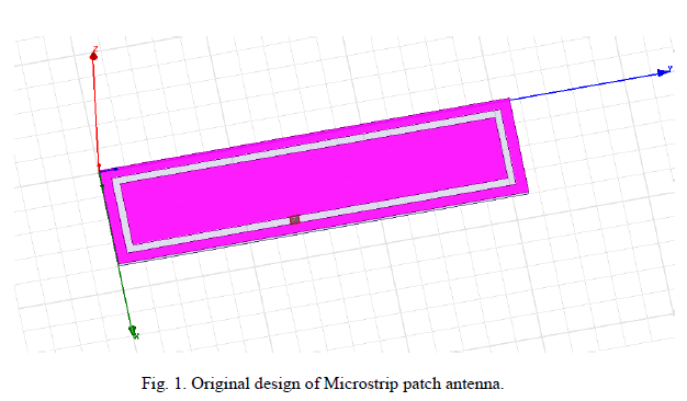
| Microstrip antenna, which is also commonly referred to as the Patch antennaR[3]. Patch antenna can be printed directly on the circuit board. Rectangular patch antennas are narrowband - the bandwidth of rectangular microstrip antennas are typically 3%. Secondly, the Microstrip antenna was designed to operate at 1.429-1.432GHZ frequency. The antenna comprises a rectangular patch and a rectangular ring on top of the circuit board with ground plane on the bottom and a dielectric substrate Duroid RT5880 with dielectric constant 2.2 (0.8mm thick and a loss tangent of 0.999). |
| Microstrip antennas can also be fed from underneath via a probe. The outer conductor of the coaxial cable is connected to the ground plane, and the center conductor is extended up to the patch antenna. The coaxial feed introduces an inductance into the feed that may need to be taken into account if the height h gets large (an appreciable fraction of a wavelength). In addition, the probe will also radiate, which can lead to radiation in undesirable directions. |
 |
Antenna Description |
| The dielectric loading of a microstrip antenna affects both its radiation pattern and impedance bandwidth. As the dielectric constant of the substrate increases, the antenna bandwidth decreases which increases the Q factor of the antenna and therefore decreases the impedance bandwidth. As the antenna is loaded with a dielectric as its substrate, the length of the antenna decreases as the relative dielectric constant of the substrate increases. The resonant length of the antenna is slightly shorter because of the extended electric "fringing fields" which increase the electrical length of the antenna slightly. The length of the patch L controls the resonant frequency. |
| A Feed line is used to excite by direct or indirect contact. There are many different methods of feeding and four most popular methods are microstrip line feed, coaxial probe, aperture coupling and proximity coupling. |
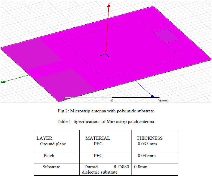
| The proposed antenna consists of a square split ring shaped radiating element fed by a CPW. The winding lengthens the current path which in turn reduces the structure size without significant efficiency degradation or disturbance to the radiation pattern. The separation distance between the arms is optimized as 5 mm to achieve the least return loss. It is worth mentioning that a smaller separation leads to an increased capacitive coupling between the arms which in turn degrades the impedance matching. The split ring monopole is fed by CPW feed, which adds the merit of fabrication simplicity since both the radiating element and ground plane are printed on the same side of the substrate. The antenna structure is printed on a 38 mmX 25 mm Kapton Polyimide substrate with a dielectric constant of 3.4 and a loss tangent of 0.002. |
 |
SPECIFIC ABSORPTION RATE |
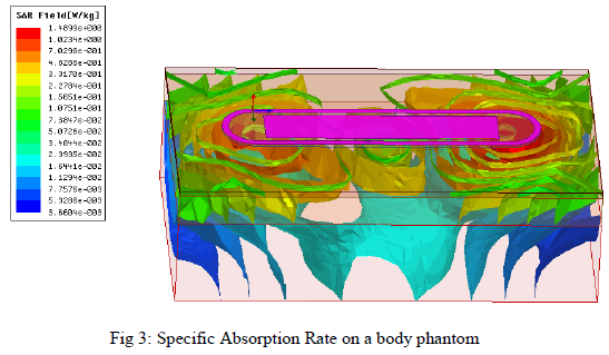
| Specific absorption rate (SAR) is a measure of the rate at which energy is absorbed by the human body when exposed to a radio frequency (RF) electromagnetic field[7]. SAR is usually averaged either over the whole body, or over a small sample volume (typically 1 g or 10 g of tissue). The typical value of SAR is to be about 1.6W/kg. The SAR value of the proposed design was evaluated using a simulation software .The calculated value is about 0.65W/kg in the existing system. In order to reduce the SAR value the polyimide substrate is placed under the ground plane for reducing the back lobes and to achieve a uniform field distribution. Such that the SAR value was reduced from 0.65W/kg3 to 0.16W/kg3 at 1.4315 GHz[6]. |
 |
CHARACTERISTIC ANALYSIS AND RADIATION PATTERN |
| Radiation Characteristics And Performance |
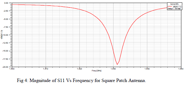
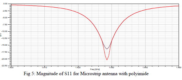
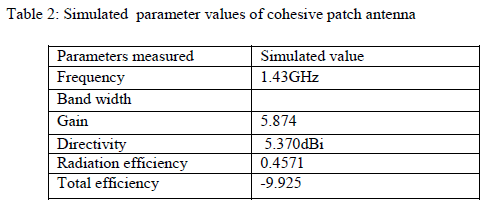
| The traditional rectangular patch antenna has the radiation efficiency of about 78.6%.whereas the existing system had the efficiency of about 85.3% in free space and 44.7% when placed on human tissue phantom, with coaxial feed . Thus the efficiency is increased in the proposed system by 89% The response of magnitude of S11 verses frequency curve clearly explains the return loss. The simulated results shows the frequency dip obtained exactly at 1.429GHz. |
 |
 |
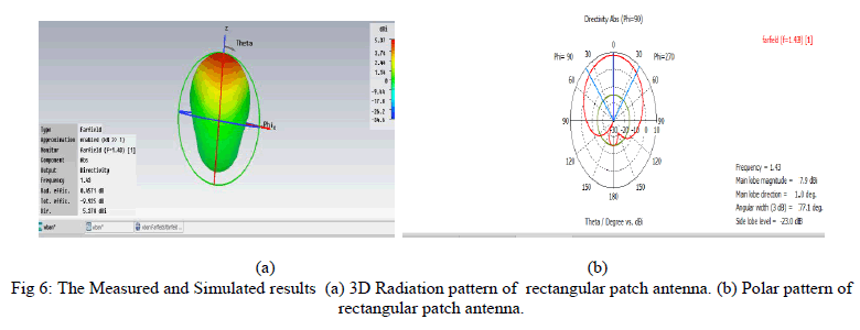
| An antenna radiation pattern or antenna pattern is the mathematical function or the graphical representation of the radiation properties of the antenna as a function of space coordinates .And radiation intensity in a given direction is the power radiated from an antenna per unit solid angle. The simulated radiation characteristics of cohesive strip is obtained as given in the below figure. |
 |
| A. Coaxial Probe Feed |
| This is a common feed technique has been carried in existing system. Here the outer conductor is connected to ground plane and the inner conductor of coaxial connector is extends through dielectric substrate and attached to patch. Inner conductor of coaxial cable transfers the power from strip line to microstrip antenna from slot in to the ground plane[5]. Placing of feed position is important in order to have best matching with input impedance. Here measurement is applied at (0mm, 9.2mm). It provides narrow bandwidth performance and it is difficult to design for thick substrate. Hence the proposed system is carried with coplanar waveguide feed method. |
 |
| B. Current Field Distribution |
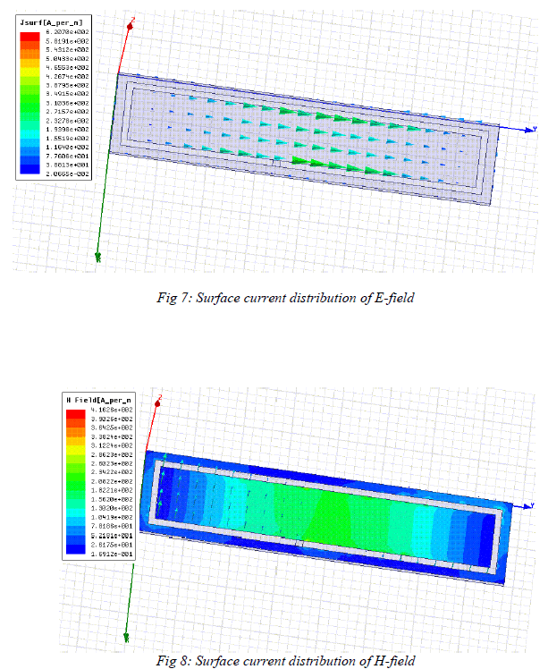
| The fringing fields around the antenna can help to explain how the microstrip antenna radiates. The fringing E-fields on the edge of the microstrip antenna add up in phase and produce the radiation of the microstrip antenna[3]. Hence microstrip antenna's radiation arises only from the fringing fields, which are due to the advantageous voltage distribution; thus the radiation arises due to the voltage and not the current. The patch antenna is therefore a "voltage radiator", as compared to the wire antennas, which radiates because the current add up in phase and are therefore they are "current radiators". |
 |
CONCLUSION |
| The proposed flexible antennas are mainly planar ones, specifically microstrip patch antennas, because they mainly radiate perpendicularly to the planar structure and also theirground plane efficiently shields the human body. The bandwidth and efficiency performance of a planar microstrip antenna is mainly determined by the substrate dielectric constant and its thickness.The low dielectric constant reduces the surface wave losses that are tied to guided wave propagation within the substrates. Therefore, lowering the dielectric constant increases spatial waves and hence increases the impedance bandwidth of the antenna. However, these are widely used in telemedicine application with the reduced SAR and high radiation efficiency. |
References |
|