ISSN ONLINE(2319-8753)PRINT(2347-6710)
ISSN ONLINE(2319-8753)PRINT(2347-6710)
| Ashwini A Kota1, U R Awari2 and Priti R Satarkar3 P.G. Student, Department of Civil Engineering, AISSMS College of Engineering, Pune, Maharashtra, India1 Assistant Professor, Department of Civil Engineering, AISSMS College of Engineering, Pune, Maharashtra, India 2 Assistant Professor, Department of Civil Engineering, AISSMS College of Engineering, Pune, Maharashtra, India 3 |
| Related article at Pubmed, Scholar Google |
Visit for more related articles at International Journal of Innovative Research in Science, Engineering and Technology
Civil and structural engineers have always preferred conoidal configuration, which is a ruled and aesthetically pleasant shape. The introduction of laminated composite as the structural material has provided the impetus to explore the different behavioural aspects of composite conoids. But the variation of curvature is the major difficulty encountered in the analysis of these shells. Keeping above point in mind, a finite element analysis is carried out using an eight noded isoparametric element with five degrees of freedom per node together with Sanders’ strain displacement relationships. Benchmark problems are solved to validate the present approach and a wide variety of composite conoidal shell problems with cross ply laminates are solved by varying aspect ratio and degree of truncation for different the stacking sequence and clamped boundary condition under uniformly distributed pressure. Results are presented for truncated and full conoid and a set of conclusions are arrived at based on a parametric study.
Keywords |
| Laminated composite, conoidal shells, aspect ratio, degree of truncation, Finite element method. |
INTRODUCTION |
| Conoidal shell configurations are aesthetically appealing, structurally stiff, and they may be used for covering large column free spaces. The greatest advantage of conoids from the construction point is that they are easy to cast as the surfaces are ruled. These shells provide uniform lighting to the covered area, and are more suitable when greater rise is needed at one end. Naturally, these forms received importance from the engineers and research on conoidal shells dates back to seventh decade of the twentieth century. The advent of the laminated composites as an advanced structural material of high specific strength and stiffness has provided new impetus to the research about conoidal shells. But the variation of curvature is the major difficulty encountered in the analysis of these shells. From the research it is clear that work on laminated composite structures has been taken up by some researchers. But no work has been found on effect of different aspect varying degree of truncation ratio for laminated composite conoidal shells. As these shells are very important industrial roofing units used extensively in the industry. Aspect ratio and degree of truncation is the major factor leading to variation of curvature which might affect the bending stiffness of such shells. Hence, in this project, a study of the bending behaviour of laminated composite conoidal shells is carried out under uniformly distributed pressure with cross ply laminates having different antisymmetric and symmetric stacking sequences by varying aspect ratio and degree of truncation for clamped boundary conditions. |
II. MATHEMATICAL FORMULATION |
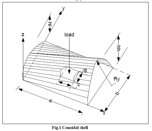
| A laminated composite conoidal shell as shown in figure 1 of uniform thickness h, radius of curvature Ry, and twist radius of curvature Rxy is considered. Keeping the total thickness the same, the thickness may consist of any number of thin laminae, each of which may be arbitrarily oriented at an angle θ with reference to the x-axis of the co-ordinate system. The generalized constitutive equations for the shell are given by (refer list of notations): |
 |
| The force and moment resultants are expressed as: |
 |
| --------(3) |
| The stiffness coefficients are defined as: |
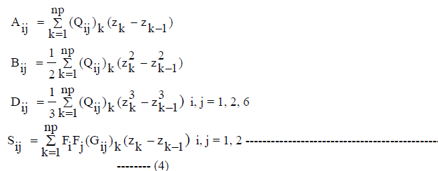 |
| Where Qij are elements of the off-axis elastic constant matrix, which are derived by appropriate transformation of onaxis matrix which contains the basic elasticity terms of the laminae as reported earlier [10]: |
 |
 |
| The strain-displacement relations on the basis of improved first order approximation theory for thin shell are established as: |
 -------- (6) -------- (6) |
| Where the first vector is the mid-surface strain for conoidal shell and the second vector is the change of curvature due to loadings. These are given, respectively, by: |
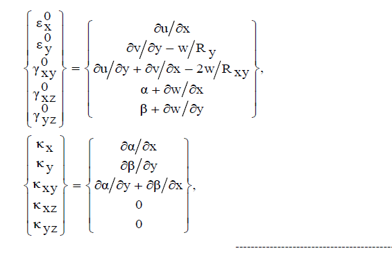 ---------- (7) ---------- (7) |
| The radius of curvature may be evaluated by differentiating the surface equation of shell in the form z=f(x, y) and for shallow shells, which are taken up for the present study, the same may be expressed as: |
 |
| B. Finite Element Formulation [10] |
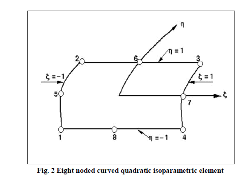
| 1) Finite Element Formulation for the Shell Element: An eight noded isoparametric curved quadratic shell element with five degrees of freedom u, v, w, α, β at each node (displacements along x, y and z axes and rotations about y and x axes) is used in the present shell analysis as appears in Reference [10]. |
| 2) Element Stiffness Matrix |
| The strain-displacement relations when cast in the terms of finite element formulation assume the following form: |
 |
| Where, |
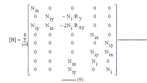 |
| The element stiffness matrix is: |
| [Kshe] = ∫ ∫[B]T[D][B]dxdy -------------------------------------------------------------------- (10) |
| The two-dimensional integration is carried out by reduced integration using 2x2 Gauss quadrature, because the shape functions are derived from cubic interpolation polynomial |
| 3) Element Load Vector: The consistent load vector {Pe} is given by: |
 |
| Where , {q}={ 0 0 q 0 0 } for transversely loaded shell and scalar q is the intensity of uniformly distributed transverse load. The area integral is evaluated by Gauss quadrature like the stiffness matrix. |
| 4) Solution Procedure: The element stiffness matrix and the element load vectors are assembled to get the global matrices, on which the boundary conditions are imposed by deleting the rows and columns of the above matrices corresponding to zero boundary values. Thus the basic problem of statics takes the form: |
 |
| Where [K] is the overall stiffness matrix and {d} and {P} are generalized displacement and load vectors, respectively. The above equation is solved by the Gauss elimination technique, and from the global displacement vector {d} thus obtained, the element displacement vectors {de} are calculated. Using {de} in Equation (8) the strains are evaluated at the Gauss points, which when put in equation (1) the generalized force and moment resultants are obtained at those points. These values are extrapolated to obtain the nodal values of the forces and moments |
III. NUMERICAL EXAMPLES |
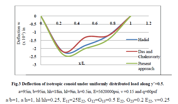
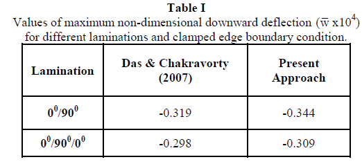
| The correctness of the present approach is confirmed by solving two benchmark problems. The first one concerns deflection of isotropic conoidal shell under uniformly distributed loading, which was solved earlier by Hadid and Das and Chakravorty (10). The results of the first benchmark problem are presented graphically in figure, where deflections at different sections are plotted. The second benchmark problem, regarding bending of laminated composite conoidal shells was solved earlier by Das & Chakravorty (10). Table I contains values of maximum non-dimensional downward deflection of 00/900 and 00/900/00 laminates obtained by Das & Chakravorty (10) and by the present authors. Various other problems which are authors’ own are solved to study the bending behaviour of laminated composite conoidal shells under uniformly distributed pressure with clamped boundary conditions and anti-symmetric and symmetric stacking sequences by varying aspect ratio and degree of truncation. |
IV. NUMERICAL RESULTS AND DISCUSSION |
| The results of the comparative problems and then of the additional examples are discussed in the following sections. |
| A. Comparative Problems |
| The results of first benchmark problem are presented graphically in fig. where the deflections at different sections are plotted. The graph obtained by Hadid and Das and Chakravorty (10) and that obtained by the present method showed very close agreement. This confirms the correct incorporation of conoidal shell curvature in the present approach. |
 |
| The results of second problems are shown in the table I which showed the close agreement of present and benchmark results. Hence the correctness of the laminated shell formulation is established. |
 |
| B. Additional Examples |
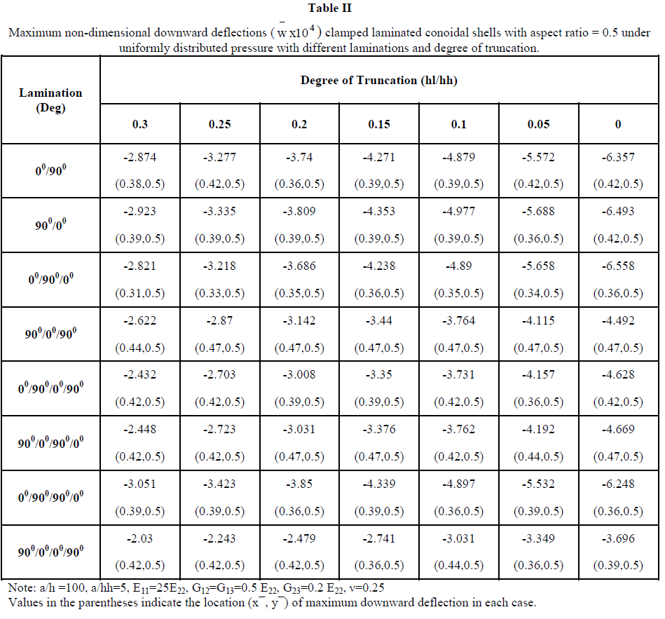
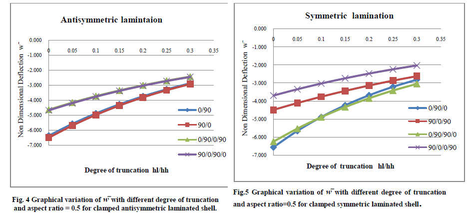
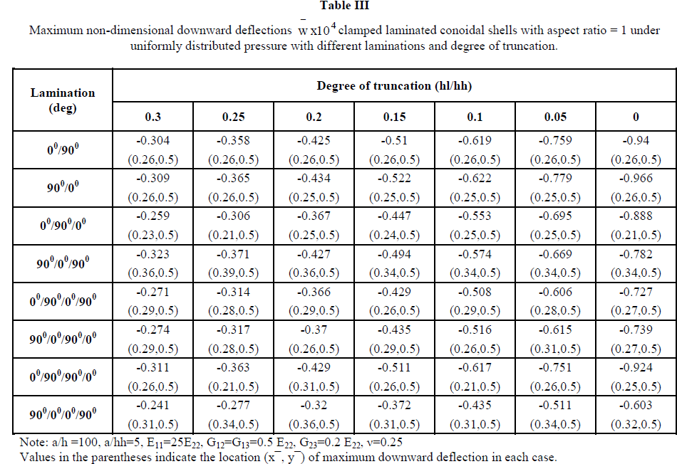
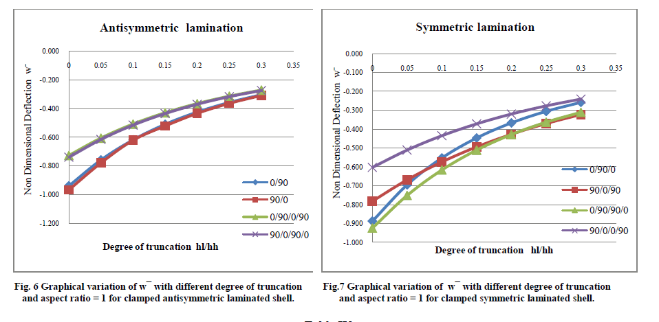
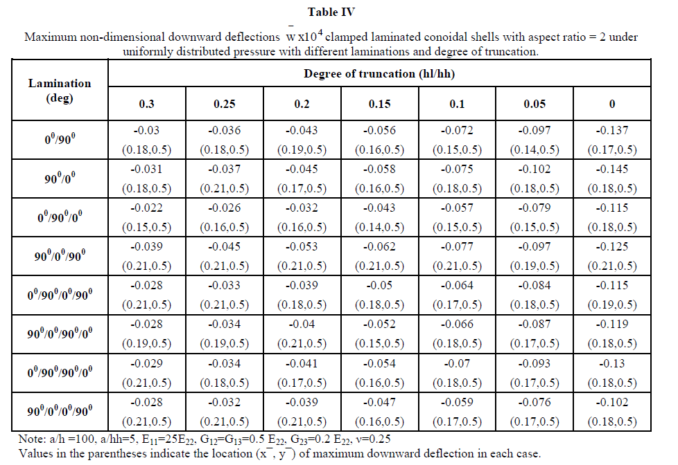
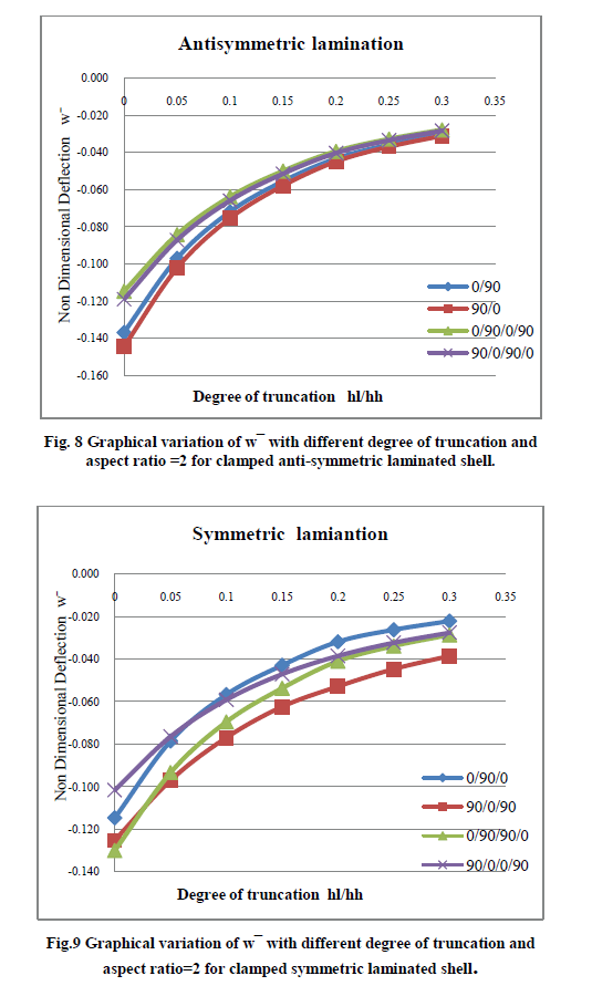
| Tables II, III and IV and Figs. 4-9 present the results of the additional examples of maximum transverse nondimensional downward deflections of laminated having different anti-symmetric and symmetric stacking sequences by varying aspect ratio and degree of truncation for clamped boundary conditions, these examples are taken up for discussion in the following sections. |
| 1. Behaviour of Clamped Shells under Uniformly Distributed Pressure: Maximum non-dimensional downward deflection for clamped boundary conditions under uniformly distributed pressure is shown in Table II, III and IV. From the observation of results it is seen that the deflection decreases with increase in degree of truncation and aspect ratio. It shows that the bending stiffness of the clamped conoidal shell increases with increase in aspect ratio. The results also lead to infer that a truncated conoidal shell is stiffer than a full conoid from bending point of view and this stiffness increases further with the increase of hl/hh Ratio. |
| 2. Antisymmetric vs. Symmetric lamination: The symmetric laminates are found to be stronger than the antisymmetric laminates with respect to bending stiffness for different aspect ratio and degree of truncation shown in Fig (4-9). The superior performance of (900/00/00/900) lamination scheme having four symmetric layers is observed from the lowest value of wÃÅÃ⦠out of all the values furnished in Table II& III. But for aspect ratio =2 it shows lower deflection only for hl/hh=0 and hl/hh=0.05 as compared to other lamination schemes. The non-dimensional downward deflection of the two anti-symmetric four layered lamination scheme (00/900/00/900) and (900/00/900/00) are found to be same for different aspect ratio and degree of truncation. Similarly, the two anti-symmetric two layers lamination scheme (00/900) and (900/00) are also showing approximately same values of w for all the values of hl/hh and a/b except for shell with a/b=2 and hi/hh=0, 0.05. |
| Effect of Increasing the Number of Layers: In order to study the effect of increase of no. of layers on maximum nondimensional downward deflection, comparative study is done for both anti-symmetric and symmetric laminations in this paper. When we compare two layered (00/900) and (900/00) and four layered (00/900)2 and (900/00)2 anti-symmetric cross plies, from composite conoidal shell roofs under uniformly distributed pressure with cross ply laminates 3. Fig. (4-9) it is seen that increase in number of plies has positive effect in decreasing the deflection values for all a/b ratios and hl/hh ratios. Comparison among three layered symmetric (00/900/00) and (900/00/900) and four layered symmetric (00/900)S and (900/00)S cross plie shells is also done and it is noticed that deflection decrease with increase in number of layers and hl/hh except for (00/900)S lamination for a/b ratio=0.5, 1shown in Fig 5&7 . But for a/b=2 deflection decrease with increase in number of layers only in case hl/hh=0 and hl/hh=0.05 (00/900)S being exception in all cases. It is also observed that a/b=2, hl/hh= (0.1-0.3) (00/900/00) showed lower deflection and (900/00/900) showed higher deflection with increase hl/hh ratio from 0.05 to 0.3 compared to other lamination schemes. |
| This observation leads to an important conclusion that if anti-symmetric laminations are considered then greater number of plies should be preferred but for symmetric ones one cannot conclude confidently whether the number of plies shall be maintained less or more in number for better performance, case specific study has to be carried out. |
 |
 |
 |
 |
 |
 |
V. CONCLUSION |
| The following are the conclusions drawn from the present study. |
| 1. The finite element formulation presented in this project can be successfully applied to analyse bending problems of laminated composite conoidal shells which is clear from the results of the benchmark problems presented in the project. |
| 2. Bending stiffness of laminated composite conoidal shells is found to increase with increase in aspect ratio. |
| 3. The results also lead to infer that a truncated conoidal shell is stiffer than a full conoidal shell from bending point of view and this stiffness increases further with increase of hl/hh ratio. |
| 4. For a clamped laminated composite conoidal shell, symmetric laminates are found to be stronger than the antisymmetric laminates with respect to bending stiffness for different aspect ratio and degree of truncation. For this boundary condition an increase in number of laminae is good for anti-symmetric laminates, but for symmetric laminates such a conclusion does not hold. |
| NOTATIONS |
| a, b length and width of shell in plan along beam and arch directions respectively |
| c, d length and width of delamination area in plan along beam and arch directions respectively |
| E11 , E22 elastic moduli |
| {F} force and moment resultant |
| G12 ,G13 ,G23 shear moduli of a lamina with respect to 1, 2 and 3 axes of fiber |
| h shell thickness |
| hh greater height of conoid |
| hl smaller height of conoid |
| {κ} curvature changes due to loading |
| κx ,κy ,κxy curvatures of shell |
| {M} moment vectors |
| Mx ,My moment resultants |
| Mxy torsion resultant |
| {N} force vectors |
| Nx ,Ny Inp lane force resultants |
| Nxy In plane shear resultant |
| q Magnitude of distributed load |
| {Q} transverse shear force vectors |
| Qx ,Qy transverse shear resultants |
| [ Qij ] elastic constant matrix |
| Ry radius of shell surface along arch (y)direction |
| Rxy radii of cross curvature of shell |
| [S] stiffness matrix in transverse shear |
| u, v, w translational degrees of freedom at each node of shell element |
| α , β rotational degrees of freedom at each node of shell element |
| {ε } inplane strain vectors |
| {γ } transverse shear strain vectors |
| {ν12 } Poisson’s ratio |
| ξ ,η local natural co-ordinates of an element |
| w non-dimensional deflection, where |
| ρ density of material |
| w vertical deflection |
| {de} element displacem |
| N1–N8 shape functions |
| x, y, z local co-ordinate axes |
| X, Y, Z global co-ordinate axes |
| α, β rotational degrees of freedom |
| εx, εy inplane strain components |
References |
|